- 38 -
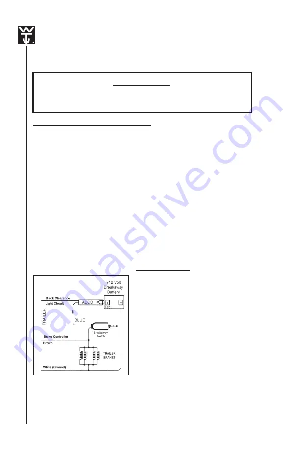
Breakaway Battery Charger Installation Instructions
(for ABCD: Accelerated Battery Charging Device)
Electrical System
IMPORTANT
Check condition of battery prior to installation and prior
to each trip.
IMPORTANT FACTS TO REMEMBER
1. Improper installation of the breakaway battery will destroy the
brake control. The negative terminal must attach to ground and
positive terminal must attach to the breakaway switch.
2. Check your breakaway system periodically to insure that wiring and
connections are secure. A short or an open circuit can result in a
no-brake condition.
3. If excessive discharging of the breakaway battery occurs, check
battery and recharge using a Heavy Duty Two Stage/Maintenance
Charger. If using a commercial (AC to DC) make certain the 12 volt
charge is limited to 1.2 amps or less.
4. The breakaway battery charger is connected to the Clearance Light
Circuit. Therefore the breakaway battery charges only when the
clearance lights are on.
(Rev. 6-02)
Battery Data Chart
• 12
Volt
• P/N 2023-5 amp/hr-max discharge
current 20 hr. rate = 250 mA
• Max Discharge Current - 40 amps
• Max charge current must be
limited to 1.2 amps
• Length = 3.54”
• Width = 2.76”
• Height = 4.13”
• Weight = 3.8 lbs.
• Terminals: Fasten Tab .187”x.032”
• Service Life: Under normal
operating conditions, 4-5 years
in standby applications or 200-
1000 charge/discharge cycles
depending upon depth of
discharge and rate of charge.
Summary of Contents for GOOSENECK LIVESTOCK
Page 40: ... 40 Electrical System Electric Hydraulic Brake Application System ...
Page 43: ... 43 Electrical System Electric Brakes Wiring Diagram ...
Page 44: ... 44 Electrical System Vacuum Hydraulic Brakes Wiring Diagram ...
Page 75: ... 75 ...
Page 78: ... 78 ...
Page 79: ... 79 ...


