background image


© by WilTec Wildanger Technik GmbH 


Item 909378pro


Page 7


http://www.WilTec.de


http://www.aoyue.eu  


12 2022-1


http://www.teichtip.de


Commissioning


1.


Plug the power cord into the socket on the back of the station.


2.


Plug the power cord into an earthed wall outlet. The station is protected against electrostatic 
discharge and must be earthed for full performance.


3.


Make sure that the power switch is off before plugging or unplugging the soldering iron cord. 
Otherwise, the circuit board may be damaged.


4.


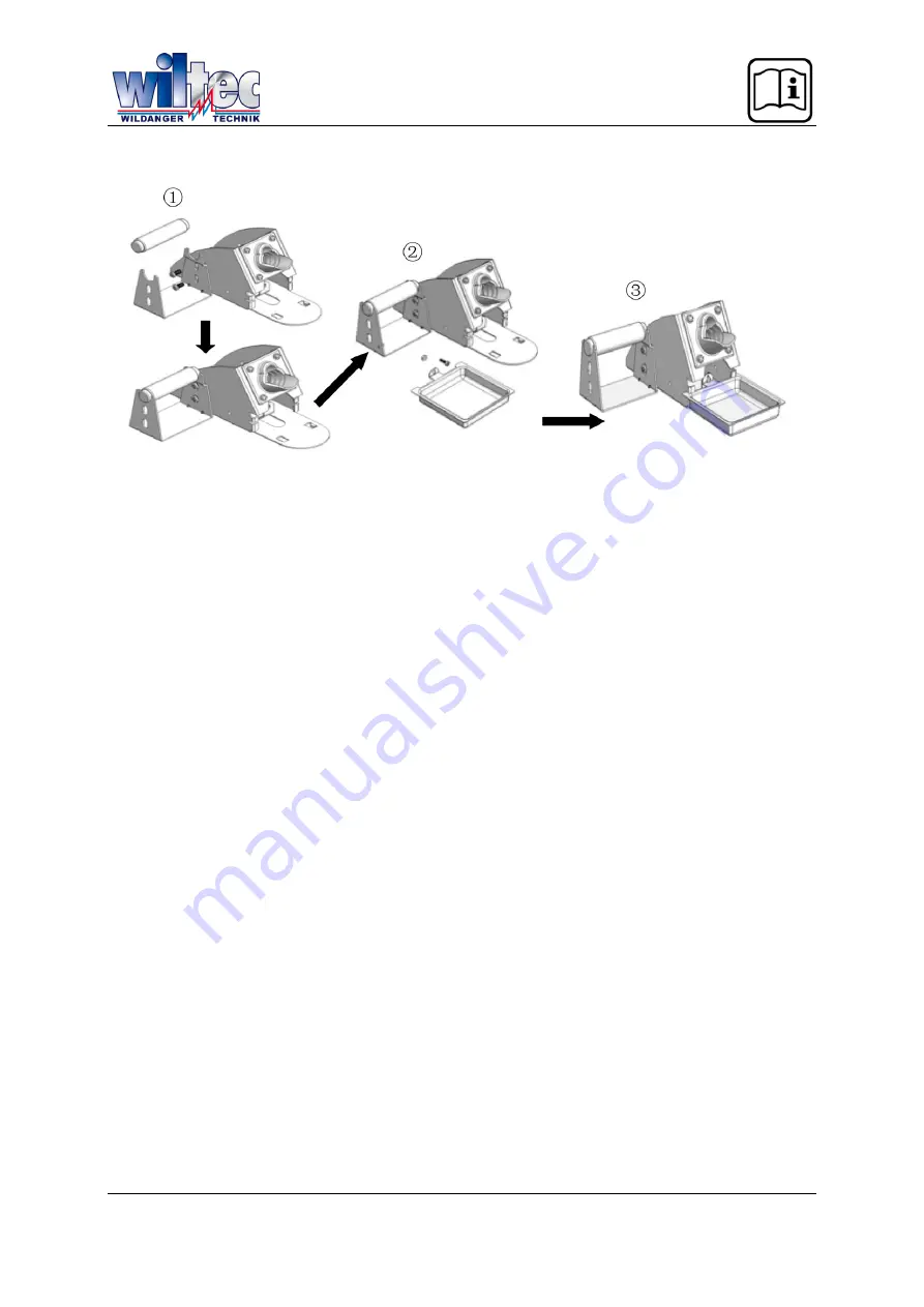
Assemble the soldering iron stand as shown.


5.


Connect the soldering iron to the 8-pin output on the bottom right of the station.


6.


Place the soldering iron on the soldering iron stand as shown.


7.


Dampen the sponge with water, squeezing out excess water beforehand. Tips can be damaged 
if used with a dry sponge.


8.


The device is now ready for operation.


Setting the temperature


1.


Switch the device on.


2.


A number between 200 and 480 is shown on the display, indicating the set temperature.


3.


The display panel then toggles and displays the actual temperature.


4.


Set the desired target temperature by pressing the Up/Down buttons.


5.


While the target temperature is being adjusted, the display shows the currently set target tem-
perature. After a few seconds, the display panel will switch to the actual temperature.


6.


The temperature control range is from 200 

 to 480 

.


Setting the digital offset


The device is equipped with a digital offset function for tip adjustment. To set the tip temperature:


1.


Set the desired working temperature.


2.


Measure the temperature of the tip using an external thermometer with a thermocouple as sen-
sor. Make sure that the sensor of the external thermometer and the tip of the soldering iron can 
keep sufficient contact. Wait for the display to reach the set temperature, then leave the tip on 
the sensor for 60


s to measure the temperature correctly.


3.


Press and hold the Set button to enter system configuration mode. Wait for the display to change 
to [01], meaning “Current tool 01.”


4.


Press  the  Set  button  again  to  enter  the  digital  offset  function.  The  display  shows  a  number 
preceded by an “A.” This means that the digital offset of the system is now being adjusted. A 
display such as “A000” indicates that the digital setting is currently set to neutral.


5.


Press the Up/Down buttons to change the digital offset. A number below zero indicates a down-
ward adjustment, a number above zero indicates an upward adjustment.


6.


Adjust the value until the reading from the external temperature sensor and the set temperature 
are the same.


Summary of Contents for 909378pro

Page 1: ...ration similar may vary depending on model Please read and follow the operating instructions and safety information prior to initial operation Technical changes reserved Illustrations functional steps...

Page 2: ...annot be ruled out entirely If you have found an error or wish to suggest an improvement we look forward to hearing from you Send us an e mail to service wiltec info or use our contact form https www...

Page 3: ...y individual part of the device is in good condition or if you can detect visible damage caused by transport If there are damages visible do not operate the device but immediately contact your vendor...

Page 4: ...ches itself on as soon as its condition has normalised Handle the device with care Never drop it never expose it to shock pushes The device contains fragile components that might be destroyed when not...

Page 5: ...n of the tool connected Suitable for lead free applications High performance heating element for rapid heat recovery Large display with digital control Programmable sleep function with auto sleep and...

Page 6: ...ating components are in their designated holders All switches must be off All connections must be made properly Menu structure Detected tool Digital offset value 70 to 70 First quick access setting 20...

Page 7: ...the display shows the currently set target tem perature After a few seconds the display panel will switch to the actual temperature 6 The temperature control range is from 200 to 480 Setting the digit...

Page 8: ...Down button 6 To save the adjusted values press the Set button repeatedly until the display shows SAVE Press the Down button to save the value and exit system configuration mode 7 The two quick access...

Page 9: ...n off the system lock again 1 With the device powered on press and hold the Up button the Set button and the Down button for more than 15 s 2 The display changes from SAFE to the set temperature value...

Page 10: ...d extends the life of the tip Device care Never leave the device idling for a long time in high temperatures Use the auto sleep feature to save energy and extend tip and heater life If the device is n...

Page 11: ...readings and then changes to Err2 Solution The heating element is damaged Replace heater or check soldering iron pin wiring 3rd problem Soldering iron tip overheated Description Soldering iron tip ge...

Page 12: ...nger Technik GmbH Item 909378pro Page 12 http www WilTec de http www aoyue eu 12 2022 1 http www teichtip de Note Suitable for all AOYUE soldering irons except lead free composite tips series inductio...

Page 13: ...ountries of the European Union and other European countries with a separate waste collection system for these devices The symbol on the packaging or the product itself indi cates that this product mus...

Reviews: