background image

24

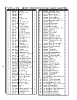
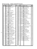
Parts Listing – Model 4300A Belt Sander

Ref # Part No.

Description                      Qty.

1

5508427

Bracket

1

2

5511833

Square Nut, M10

1

3

5051081

Spring

1

4

5051091

Sleeve

1

5

5051131

Collar

1

6

5508431

Shaft with Collar

1

7

5051151

Cap

1

8

TS-2361051 Lock Washer, M5

2

9

TS-1513051 SHFS, M5 x 25

2

10

5051721

Hand Wheel

1

11

5511818

Flat Head Screw, M5 x 6

4

12

TS-1550071 Flat Washer, M10

1

13

5508432

Tilting Table

1

14

5508450

Hand Knob

2

15

5508429

Belt Adj. Knob, M10

1

16

5511824

Drive Screw, M2 x 5

3

17

5508437

Stop Lock

1

18

5511828

Groove Pin, M5 x 45

1

19

5051351

Tilting Scale

1

20

TS-1523011 SHSS, M6 x 6

2

21

5511827

Groove Pin, M4 x 8

2

22

5051331

Segment

1

23

5511725

4200 Arbor Pulley

1

24

TS-1504061 SHCS, M8 x 30

4

25

TS-2361081 Lock Washer, M8

4

26

5508433

Trunnion

1

27

TS-1550061 Flat Washer, M8

3

28

TS-2361081 Lock Washer, M8

3

29

TS-1490041 Hex Cap Screw, M8 x 25

3

30

5508435

Stud, M10

1

31

TS-1550071 Flat Washer, M10

4

32

5508436

Acorn Nut and Handle

1

33

TS-2361061 Lock Washer, M6

3

34

TS-1482033 Hex Cap Screw, M6 x 18

3

35

5508439

Reload Bushing, M54

1

36

BB-6205ZZ Ball Bearing, 6205ZZ

1

37

5508438

Bearing Housing

1

38

TS-2210951

Hex Cap Screw, M10 x 140

2

39

5051421

Key, 5 x 5 x 70

1

40

5508442

Drive Shaft

1

41

5051451

Key, 5 x 5 x 35

1

42

TS-1482034 Hex Cap Screw, M6 x 19

4

43

BB-6204ZZ Ball Bearing, 6204ZZ

1

44

5051471

Retaining Ring, S20

1

45

VB-A59

V-Belt, A59

1

46

TS-2245081 SHFS, M5 x 8

4

47

5508445

Belt Guard Assembly

1

48

4200A-048 Label, Warning

1

49

TS-1540071 Hex Nut, Full, M10

5

50

5508446

Stop Pin

1

51

5508448

Base

1

Ref # Part No.

Description                       Qty.

52

TS-2210801 Hex Cap Screw, M10 x 80

4

53

TS-1550071 Flat Washer, M10

8

54

TS-2361101 Lock Washer, M10

6

55

5051841

Garnet Belt

1

56

5508455

Deflector Plate

1

57

TS-2361051 Lock Washer, M5

2

58

TS-1513021 SHFS, M5 x 12

2

59

5508454

Drive Drum Guard

1

60

5508456

Dust Deflector

1

61

TS-2361101 Lock Washer, M10

3

62

TS-1491021 Hex Cap Screw, M10 x 20

3

63

5508457

Platen

1

64

TS-1514011 SHFS, M6 x 12

2

65

5051601A

Side Guard

1

66

TS-1540231 Hex Nut, M24

1

67

9058121

Lock Washer, Ext., M24

1

68

5051981

Spacer

1

69

5051971A

Drive Drum

1

70

5508458

Clamp Ring

1

71

4200A-077 Idler Drum Shaft

1

72

5051031

Tension Lever Pin

1

73

5051021

Belt Tension Lever

1

74

BB-6202ZZ Ball Brearing, 6202ZZ

2

75

5508461

Idler Drum Shaft with

1

Lock Nut

76

TS-2342121 Hex Nut, Nylon Lock, M12

2

77

5508460

Bearing Lock Nut

1

78

5051591A

Idler Drum Guard

1

79

5508462

Stud

1

80

5508463

Clamp Bar

2

81

5052121

Bottom Guard

1

82

TS-2361061 Lock Washer, M6

4

83

5052061B

Idler Drum Spacer

2

84

5508459

Idler Pin Bracket

1

85

TS-0367061 Roll Pin, 1/4" x 1-1/4"

2

86

5052001

Block

2

87

5052061A

Idler Drum

2

88

5508434

Pointer

1

89

5052271

Deluxe Miter Gauge

1

90

4300A-090 Label, Name

1

91

4200A-105 Label, Direction

1

92

TS-1482081 Hex Cap Screw, M6 x 40

2

93

TS-1540041 Hex Nut,Full, M6

2

94

4300A-094 Label, Warning

1

95

TS-152704 Allen Wrench, 4mm

1

Summary of Contents for 4200A

Page 1: ...ombination Disc Belt Sanders Models 4200A 4300A 4400A WHM TOOL GROUP 2420 Vantage Drive Elgin Illinois 60123 Part No 5511365 Ph 800 274 6848 Revision E2 10 04 www wmhtoolgroup com Copyright WMH Tool Group 4200A Disc Belt Sander 4300A 6 Inch Belt Sander 4400A 12 Inch Disc Sander ...

Page 2: ...de our facilities or to a lack of maintenance WMH TOOL GROUP LIMITS ALL IMPLIED WARRANTIES TO THE PERIOD SPECIFIED ABOVE BEGINNING FROM THE DATE THE PRODUCT WAS PURCHASED AT RETAIL EXCEPT AS STATED HEREIN ANY IMPLIED WARRANTIES OR MERCHANTABILITYAND FITNESSARE EXCLUDED SOME STATES DO NOT ALLOW LIMITATIONS ON HOW LONG THE IMPLIED WARRANTY LASTS SO THE ABOVE LIMITATION MAY NOT APPLY TO YOU IN NO EVE...

Page 3: ...arranty 2 Table of Contents 3 Machine and Manual Overview 4 General Specifications 5 Warnings 6 Operating Instructions 8 Maintenance 10 Setup and Installation 13 Troubleshooting 18 Wiring Diagrams 19 Replacement Parts 20 Accessories 28 ...

Page 4: ...chines are typically considered sanding machines Whatever you call them and however you use them the instructions in this manual will help you use them safely and productively You will note there are several types of electrical sys tems available for these machines All of these systems are equally effective in providing power to the grinding mechanism however local codes and the type of envi ronme...

Page 5: ...mensions w platen vertical depth W H Dimensions w platen horizontal depth W H Motor options Weight 7 3 8x14 3 4 in 187x355mm 45 down 20 up 3 8x3 4 in 9 5x19mm 6 1 4x14 3 4 in 159x375mm 6x48 in 152x1214mm 2850 SFM 19x16x57 1 2 in 475x400x1437mm 25 1 2x16x43 in 637x400x1075mm Model 4300A 1 ph 1 5HP 115 230V Model 4301A 3 ph 1 5HP 230V 460V Model 4303A 3 ph 1 5HP 230 460V connected 460 full JIC 110V ...

Page 6: ...ools in wet or damp locations Keep work areas clean and well lit 6 Special electrical precautions should be taken when working on flammable materials 7 Avoid accidental starts by being sure that the start switch is in the OFF position before plugging in the machine 8 Never leave the machine running while unattended The machine shall be shut off whenever it is not being used 9 Disconnect the electr...

Page 7: ... the workpiece or throwing of the workpiece off the wheel 11 Safety shoes which comply with ANSI Z41 1 should be worn 12 Personal hearing protection such as ear plugs or ear muffs should be used to protect against the effect of noise exposure Figure A Figure B Figure D Figure C Safety Requirements for Abrasive Sanding Machines Abrasive sanding can be hazardous to operators and by standers Sanding ...

Page 8: ...ide of the table 2 Using the pointer and scale set the angle to any re quired angle between 20o upward and 45o downward 3 Lock the lock handle To Tilt the Table to Exactly 45o 1 Flip out the stop bracket see Figure 20 2 Unlock the locking handle 3 Move the table until it contacts the stop bracket 4 Lock the table lock handle Figure 1 Locking handle for belt table Using the Indexing Lock Handle The...

Page 9: ...E MOTOR OFF BEFORE ADJUSTING THE TABLE ANGLE Figure 5 Use of the miter system Use of the Miter Gauge The miter gauge can be used on either the disc or belt surfaces to sand accurate angles on workpieces When using the gauge alone you sand a single angle However by tilting the table and using the miter gauge in combina tion with the table tilt it is possible to sand compound angles as well When gri...

Page 10: ...on handle clockwise until the belt is flat against the platen and there is no curling or buckling of the belt in the middle 11 Turn the drums by hand to see if the belt tracks more or less true JUST BECAUSE THE OLD BELT TRACKED CORRECTLY DOES NOT MEAN THE NEW BELT WILL Always check the tracking when replacing a belt 12 To adjust the tracking 12 1 Plug the machine back into the outlet or reestablis...

Page 11: ... the power to the machine to prevent acci dental start ups 2 Peel off the old abrasive disc 3 Clean the drive disc surface using naptha or a similar nonflammable solvent that will dry film free 4 Pull the protective backing half off the new abrasive disc 5 Position the new disc carefully so it is centered accu rately on the drive disc See Figure 8 6 When accurately centered remove the rest of the ...

Page 12: ...osition the drive disc so that it is no more than 1 16 inch away from the table then tighten BOTH of the set screws by inserting the hex wrench through the hole in the disc guard casting 12 Rotate the machine back onto its base and secure it with all four mounting bolts 13 Install the belt over the bottom pulley 14 Tension the belt so that when pressed in the middle of its travel it has no more th...

Page 13: ...ION OF THE MACHINE 5 Establish an electrical service connection to the ma chine This will vary according to the model purchased ALL ELECTRICAL CONNECTIONS SHOULD BE MADE BY A QUALIFIED ELECTRICIAN WHO IS FAMILIAR WITH YOUR STATE AND LOCAL CODES Many models of these ma chines make use of high voltages which pose a significant risk of serious injury or DEATH if proper knowledge and precautions are n...

Page 14: ...posite edge of the disc and measure the distance to the miter slot 5 Adjust the table by loosening the four attachment screws under the table then move the table until the distance be tween the miter slot and the disc is equal on both sides See Figure 17 6 Tighten the four attachment screws 7 Reconnect the electrical power to the machine Figure 16 Using an adjustable square to set the table parall...

Page 15: ...ard to about 15o 2 Flip out the stop bracket See Figure 21 3 Lower the table until its adjusting screw touches the stop bracket 4 Place a machinist s square against the table and belt or platen 5 If adjustment is required turn the adjusting screw Figure 20 until the table is exactly square to the platen 6 Check the pointer If it is not on 0o loosen the pointer screw and adjust the pointer until it...

Page 16: ...nders are available in a wide vari ety of electrical configurations to meet the needs of the purchaser with respect to power available and compliance with electrical codes Each machine is tested at the factory for operation before shipment and the power cord is tagged with the power requirements for the machine as shipped HOWEVER before attempting any electrical hookup you should be certain 1 The ...

Page 17: ...rsion process Circuit Protection Where the service branch is protected with a fuse or circuit breaker that has too high a value to offer protection to the motor supplied a fuse or circuit breaker box should be used at the point where the machine connection is made and the time delay fuse or circuit breaker should be a value just slightly higher than the maximum load current draw Three Phase Electr...

Page 18: ...or only in one area of the disc 3 Incorrect abrasive material or grit size 1 Allow the belt to do the cutting Excessive pressure only dulls the grit and removes it from the cloth 2 Use all the surface areas of the abrasive cloth 3 Check with your abrasives supplier for rec ommendations on the type and coarse ness of the abrasive required for the workpieces you are sanding or grinding 1 Replace the...

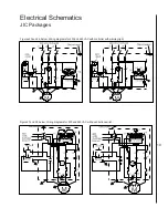
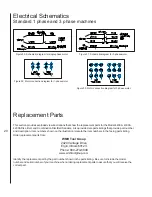
Page 19: ...res 25 and 26 below Wiring diagrams for 230 and 460 VAC with controller with warning light Figure 27 and 28 below Wiring diagrams for 230 and 460 VAC with push button switch Electrical Schematics JIC Packages ...

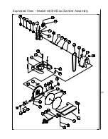
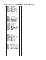
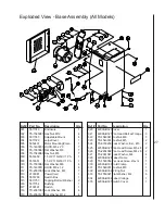
Page 20: ... 4400A 4300A 4200A Disc Belt and Combination Disc Belt Sanders Also provided are parts listings that provide part number and description Item numbers shown on the illustration relate to the item numbers in the facing parts listing Order replacement parts from WMH Tool Group 2420 Vantage Drive Elgin Illinois 60123 Phone 800 274 6848 www wmhtoolgroup com Identify the replacement part by the part num...

Page 21: ...21 Exploded View Model 4200A Belt and Disc Sander Assembly ...

Page 22: ... Cap Screw M10 x 80 4 53 5515292 Flat Washer M10 8 54 TS 2361101 Lock Washer M10 6 55 5051841 Garnet Belt 1 Ref Part No Description Qty 56 5508455 Deflector Plate 1 57 TS 2361051 Lock Washer M5 2 58 TS 1513021 SHFS M5 x 12 2 59 5508454 Drive Drum Guard 1 60 5508456 Dust Deflector 1 61 TS 2361101 Lock Washer M10 3 62 TS 1491021 Hex Cap Screw M10 x 20 3 63 5508457 Platen 1 64 TS 1514011 SHFS M6 x 12...

Page 23: ...23 Exploded View Model 4300A Belt Sander Assembly ...

Page 24: ...g S20 1 45 VB A59 V Belt A59 1 46 TS 2245081 SHFS M5 x 8 4 47 5508445 Belt GuardAssembly 1 48 4200A 048 Label Warning 1 49 TS 1540071 Hex Nut Full M10 5 50 5508446 Stop Pin 1 51 5508448 Base 1 Ref Part No Description Qty 52 TS 2210801 Hex Cap Screw M10 x 80 4 53 TS 1550071 Flat Washer M10 8 54 TS 2361101 Lock Washer M10 6 55 5051841 Garnet Belt 1 56 5508455 Deflector Plate 1 57 TS 2361051 Lock Was...

Page 25: ...25 Exploded View Model 4400A Disc Sander Assembly ...

Page 26: ...ing 1 19 4200A 105 Label Direction 1 20 4400A 020 Label Warning 1 21 4400A 021 Label Warning 1 22 TS 1540071 Hex Nut Full M10 4 23 TS 2210801 Hex Cap Screw M10 x 80 4 24 TS 1550071 Flat Washer M10 8 25 5508447 Base 1 26 TS 1550071 Flat Washer M10 2 27 TS 2361101 Lock Washer M10 4 28 5508450 Hand Knob 2 29 5508451 Clamp with Pins 2 30 4200A 090 Roll Pin M6 x 45 4 31 5508462 Stud 2 32 5508453 Disc G...

Page 27: ...4 5514703 Switch Box 1 315 5511753 Tapping Bolt w Washer 2 316 5511754 Bushing 1 317 9139391 Switch 1 318 TS 2361081 Lock Washer M8 4 319 TS 2360121 Flat Washer M12 4 Ref Part No Description Qty 320 4200A B320Cover 1 321 4200A B321Pan Head Bolt w Flange 3 322 TS 1540041 Hex Nut M6 3 323 TS 1540031 Hex Nut M5 2 324 TS 0733203 Lock Washer Ext 10 2 325 4200A B325Pan Head Screw M5 x 8 2 326 TS 2284082...

Page 28: ... DUST COLLECTION SYS TEM BEFORE PERFORMING MAINTENANCE FAILURE TO DO SO MAY RESULT IN INJURY TO THE OPERATOR AND OR MAINTENANCE PERSONNEL DO NOT OPERATE THE DUST COLLECTION SYSTEM WITH THE COVER REMOVED INJURY TO FINGERS AND HANDS FROM THE FAN BLADES AND INGESTION OF LOOSE FITTING CLOTHING INTO THE AIR INLET WITH RESULTANT INJURY IS ALSO POSSIBLE Cleaning Periodically dispose of accumulated chips ...

Page 29: ...oosen the set screw 22 Remove the fan 21 from the shaft of the motor 25 Remove the key 23 from the motor shaft 8 Use a flat bladed screwdriver to hold the flat head screws 28 in inner fan housing Remove four nuts 26 and lock washers 27 from the flat head screws 28 in the motor mounting lugs Assembly Assembly is the reverse of disassembly Observe the following during assembly 1 Assemble the motor 2...

Page 30: ...30 Exploded View Model 5511885 Dust Collection System FRONTVIEW REARVIEW 15 14 22 21 16 24 28 9 23 25 26 20 19 27 12 13 18 17 11 10 5 6 7 8 4 1 2 3 ...

Page 31: ...Washer Lock 4 14 5514743 Screw Hex Head 4 15 5514744 Spacer 1 16 5514745 Housing Outer Fan 1 17 5514746 Nut Hex 5 18 5514747 Washer Lock 5 Ref Part No Number Description Qty 19 5514748 Screw Hex Head 5 20 5514749 Strap Guard 1 21 5514750 Fan 1 22 5514751 Screw Set 1 23 5514752 Key 1 24 5514753 Housing Inner Fan 1 25 5514754 Motor 1 26 5514755 Screw Hex Head 4 27 5514756 Seal Tape AR 28 5514757 Swi...

Page 32: ...WMH Tool Group 2420 Vantage Drive Elgin Illinois 60123 Phone 800 274 6848 www wmhtoolgroup com ...

Reviews: