background image

4

PREPARATION

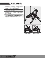
1.   Using the wrench provided, remove the hex bolt, lock washer, 

and washer from the base. Using the wrench provided, 

attach the leg to the base with the hex bolt, lock washer, and 

washer. Repeat process for the remaining legs.

2.   Attach the handle the the push block assembly and link bars 

with the locking pins.

Note: Configuration 1 is for in use and Configuration 2 is for 

locking the handle and push assembly in up position.

Config. 1 - in use

Config. 2 - locked

Note: There are left and right legs.

Summary of Contents for KATTEX TLC-1

Page 1: ...or call 973 295 3899 DO NOT send unit to WINCO without first contacting our customer service department For California Customers WARNING Cancer and Reproductive Harm www P65Warnings ca gov Visite www...

Page 2: ...ACTORY AUTHORIZED SERVICE PROVIDER SHOULD HANDLE ALL MAINTENANCE AND REPAIR BEFORE DOING ANY MAINTENANCE OR REPAIR FOLLOW SERVICE SET UP ARRANGEMENT AVERTISSEMENT TOUTE INSTALLATION R GLAGE MODIFICATI...

Page 3: ...uncertainty about a particular task or the proper method of operating this equipment ask an experienced supervisor Note Please remember that this manual and the warning labels do not replace the need...

Page 4: ...ase with the hex bolt lock washer and washer Repeat process for the remaining legs 2 Attach the handle the the push block assembly and link bars with the locking pins Note Configuration 1 is for in us...

Page 5: ...ong quick thrust bring the push assembly down to force the produce through the blades 4 Clean the machine after cutting is completed in accordance with the cleaning instructions If the unit fails to p...

Page 6: ...ring optimal performance and longevity Minimize the use of alkaline or acidic cleaners as they may cause pitting and dulling of the finish WARNING THE BLADES ARE VERY SHARP PLEASE USE CAUTION WHEN HAN...

Page 7: ...AT BS OT 4 3 Push Block Assembly 1 4 Clip 2 5 Blade Assembly TLC 1 B 1 6 Base 1 7 Leg 2 Left 2 Right 4 8 Rubber Foot KAT FT 4 9 Dual Sided Wrench KAT WR 1 10 Locking Pin 3 11 Hex Bolt Locking Ring Was...

Page 8: ...ge due to excess water fire normal wear improper set up and use Periodic maintenance is not covered This warranty is not in force until such time as a properly completed and digitally signed Installat...

Reviews: