17
60706-229/G
TRANSFER SWITCH & ENGINE-GENERATOR
Automatic (remote) Operation
This procedure checks the electrical operation of the
automatic transfer switch. If the actual operation does not
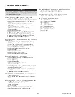
follow procedure, consult the trouble-shooting section in
the transfer switch manual.
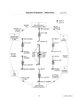
1. Turn on the preferred source (utility) circuit breaker.
The Utility Acceptable Light should now come on, as
well as the Load on Utility Light. If those lights fail to
come on, recheck your incoming power to ensure you
have 240 Volts nominal. If not, troubleshoot your utility
source before continuing.
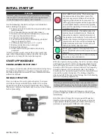
2. Press and release the Auto button on the engine
control module (ECM). The auto mode icon will appear
on the screen. The unit is now ready to be operated
from the Automatic Transfer Switch.
3. Turn on the alternate source (generator) circuit
breaker.
WARNING: PERSONAL INJURY HAZARD
Install front cover in transfer switch before operation.
An electrical system fault could cause a flash and severe
personal injury.
The digital controller provides sensing, timing, and control
functions for the ATS. This micro-processor-based controller
includes built-in control buttons and status lights for control
of the ATS and the generator.
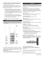
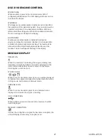
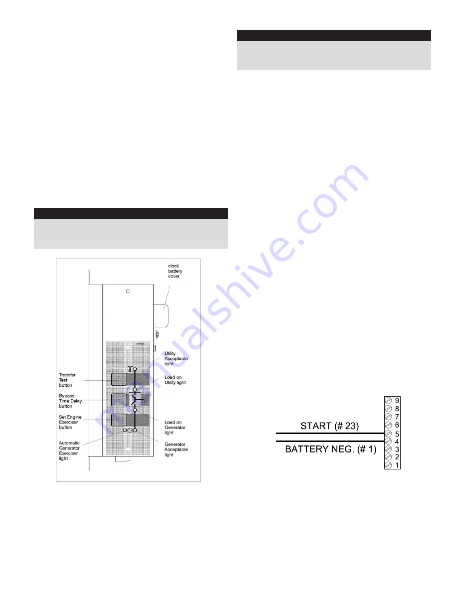
PUSH BUTTONS
On the front control display are the three push buttons that
control the operation of the generator and the ATS.
CAUTION
Before using the transfer test button, be sure that
conditions are safe for running the generator and for load
tester.
TRANSFER TEST
Use this button to test the system. This operation starts
the generator and transfers the load. The controller is
shipped with a load transfer set by default. Changing the
exercise without a load will be discussed later. Be sure that
conditions are safe to do this operation.
BYPASS TIME DELAY
Use this button to cancel the active time delay or exercise
period (stops the generator after cool-down).
SET ENGINE EXERCISER
Use this button to set the automatic exerciser.
INDICATOR LIGHTS
On the front control display are five lights that indicate the
status of the sources and the ATS.
UTILITY ACCEPTABLE
This light indicates that tehe utility voltage is acceptable for
connection to the loads.
GENERATOR ACCEPTABLE
This light indicates that the generator voltage and
frequency is acceptable for connection to the load.
LOAD ON UTILITY
This light indicates that the generator voltage is acceptable
for connection to the load.
AUTOMATIC GENERATOR EXERCISER
This light indicates the status of the generator exerciser:
• Blinks during the exercise period (including cool down)
• Stays on when the exerciser has been set.
• Is off when the exerciser has not been set.
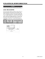
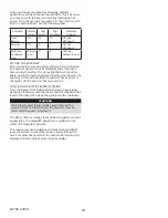
GENERATOR STARTING CONTACTS
Disconnect the generator battery. Connect the generator
starting wires #1 (battery -) to terminal 4; wire #23 (start) to
terminal 5 of the TB7 terminal block. This is removable for
convenient connections.
GENERATOR EXERCISER CIRCUIT
The automatic generator exerciser is configured to
automatically exercise the generator for 20 minutes once
every week.
In order to set and test the exercise circuit the AUTO button
on the generator control panel must be on.
EXERCISE WITH OR WITHOUT LOAD
The transfer switch can be set up to exercise the generator
Summary of Contents for PSS20B2W/A
Page 19: ...19 60706 229 G...
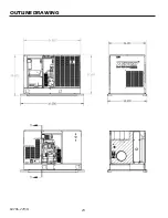
Page 24: ...24 60706 229 G OUTLINE DRAWING...
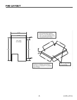
Page 25: ...25 60706 229 G PAD LAYOUT 60706 229 23 12270 01 60706 229 ET A ENGINE GENERATOR SET PAD LAYOUT...
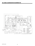
Page 26: ...26 60706 229 G AC AND DC GENERATOR SCHEMATIC...
Page 27: ...27 60706 229 G AC WIRING SCHEMATIC PSS20 3 A PSS20 17 A PSS20 18 A PSS20 4 A...


