background image

25

60706-229/G

PAD LAYOUT

12270-01

22

60706-229

23

12270-01

60706-229

ENGINE GENERA

TOR SET

LA

YOUT ULPSS20B2W/A

ENGINE GENERATOR SET

PAD LAYOUT

Summary of Contents for PSS20B2W/A

Page 1: ...ld ever need to contact us on this unit it will help us to respond to your needs faster MODEL __________________________________________________ SERIAL NUMBER _________________________________________...

Page 2: ...Y INSTALLATION 11 SERVICING BATTERIES BATTERY CHARGING CONNECTING BATTERY CHARGER GENERATOR CONNECTIONS WINCO UL ATS ASCO 185 AC ELECTRICAL CONNECTIONS 13 ASCO 185 UL SWITCH DC ELECTRICAL INTERCONNECT...

Page 3: ...NCO generator You have selected a high quality precision engineered generator designed and tested to give you years of satisfactory service To get the best performance from your new generator it is im...

Page 4: ...t must be mixed with fresh air A Operate only in well ventilated areas B Never operate indoors including attached garages C Never operate the unit in such a way as to allow exhaust gases to seep back...

Page 5: ...Vapor 2520 BTU FT CF HR 328 130 5 BTU HR 328 000 329 000 GAL HR N A 3 61 Based on full load operation LP TANK SIZING Tank Temperature Tank Size 60 F 16 C 150 Gallons 32 F 0 C 250 Gallons 0 F 18 C 500...

Page 6: ...nt The ATS also contains the power failure sensing circuitry necessary to start and stop the engine generator set The transfer switch is also equipped standard with a 3 second start delay and a 15 sec...

Page 7: ...d quantity of oil required is listed in the engine operator s manual and under the service tab in this manual This unit was shipped with most of the oil removed The engine normally holds 80 ounces 2 5...

Page 8: ...ormation in this manual is offered only as a guide to finalizing your installation plans WARNING PERSONAL INJURY The enclosures on these units can become very hot adjacent to the exhaust areas Special...

Page 9: ...egulator Consult your local fuel supplier for your exact requirements The appropriate line size from the following table is then installed from the low pressure regulator to the generator set Feet Siz...

Page 10: ...0 15 lbs 7 11 in 4 6 oz 7 11 in 4 6 oz No load Line PSI 10 15 lbs 7 11 in 4 6 oz 7 11 in 4 6 oz Full load Line PSI 10 15 lbs 7 11 in 4 6 oz 7 11 in 4 6 oz Natural gas Ref 2 3 4 Unit off 2 PSI 7 11 in...

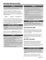
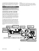
Page 11: ...first and the positive cable last Failure to connect and disconnect in the proper sequence can cause equipment damage Observe polarities connect the positive battery terminal to the cable from the eng...

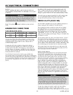
Page 12: ...ordance with the United States National Electric Code These AC wires can be run in the same conduit as the other AC leads from the generator It is suggested that this circuit be fused for 15 Amps Term...

Page 13: ...the terminals L2 L6 The normal line power terminals in the ATS are marked PREFERRED L1 L5 The hot line power leads are L1 and L3 from the utility power supply They are connected to terminals L1 and L...

Page 14: ...re to be powered under emergency power failure conditions an additional distribution panel designated emergency distribution panel must be installed All selected emergency circuits are removed from ma...

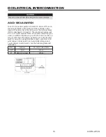
Page 15: ...through 9 These terminals will accept 22 14 AWG stranded wire It is recommended that you use 16 AWG for distances up to 200 feet You need to run two 2 wires from the engine generator set to the transf...

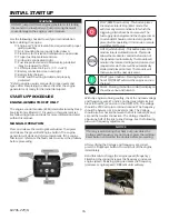
Page 16: ...is ready for the initial start up test START UP PROCEDURE ENGINE GENERATOR SET ONLY The engine control module ECM is manufactured by Deep Sea Electronics Model 3110 is used on this generator set See...

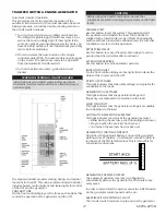
Page 17: ...e system This operation starts the generator and transfers the load The controller is shipped with a load transfer set by default Changing the exercise without a load will be discussed later Be sure t...

Page 18: ...ing the exercise period including cool down The light stays on to indicate that the exerciser has been set If the light is off the exerciser has not been set CANCELING AN ACTIVE EXERCISE PERIOD Press...

Page 19: ...19 60706 229 G...

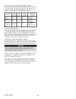
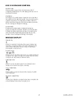
Page 20: ...Auxiliary inputs can be user configured and will display he message as written by the user Fail to Start The engine has not fired after the preset number of start attempts Fail to Stop The module has...

Page 21: ...The fault must be removed and the Stop Reset button pressed to reset the module The icon will appear flashing in the display MODULE DISPLAY TIMER ICON When the module is controlling the engine startin...

Page 22: ...and not burned or pitted ENGINE GENERATOR SET Service the engine in accordance with the engine manufacturer s manual provided with your new equipment Routinely remove debris and dirt from around the...

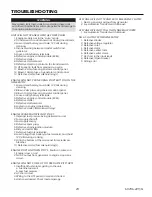
Page 23: ...ked up engine generator set 9 Defective starter fuel solenoid relays ENGINE CRANKS BUT WILL NOT START 1 Improper fuel pressure being delivered to unit 2 Fuel supply shut off 3 Fuel supply empty 4 Defe...

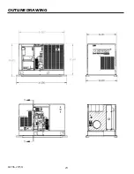
Page 24: ...24 60706 229 G OUTLINE DRAWING...

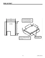
Page 25: ...25 60706 229 G PAD LAYOUT 60706 229 23 12270 01 60706 229 ET A ENGINE GENERATOR SET PAD LAYOUT...

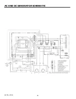
Page 26: ...26 60706 229 G AC AND DC GENERATOR SCHEMATIC...

Page 27: ...27 60706 229 G AC WIRING SCHEMATIC PSS20 3 A PSS20 17 A PSS20 18 A PSS20 4 A...

Page 28: ...does not cover travel time mileage or labor for removal or re installation of WINCO product from its application Normal wear and tear Costs of rental equipment WINCO does not warrant engines Engines a...

Reviews: