13
OPM-117/D
Wire Temperature Rating
Cu Conductor
Al Conductor
kW
Volts
PH Amp
75°C
90°C
75°C
90°C
60
120/240
1
250
300
MCM
250
MCM
500
MCM
350
MCM
60
120/208
3
200
4/0 AWG
3/0
AWG
300
MCM
250
MCM
60
120/240
3
175
3/0 AWG
2/0
AWG
250
MCM
4/0
AWG
60
277/480
3
90
#2 AWG
#3 AWG
1/0
AWG
#2
AWG
90
120/240
1
400
600
MCM
500
MCM
(NOTE 1)
600
MCM
90
120/208
3
300
500
MCM
350
MCM
600
MCM
500
MCM
90
120/240
3
300
300
MCM
250
MCM
500
MCM
350
MCM
90
277/480
3
150
2/0 AWG
1/0
AWG
4/0
AWG
3/0
AWG
Note 1 - Two 250 MCM may be used.
For additional information on wire sizing refer to table 310-
16 of the National Electrical Code ANSI/NFPA 70.
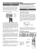
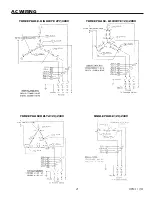
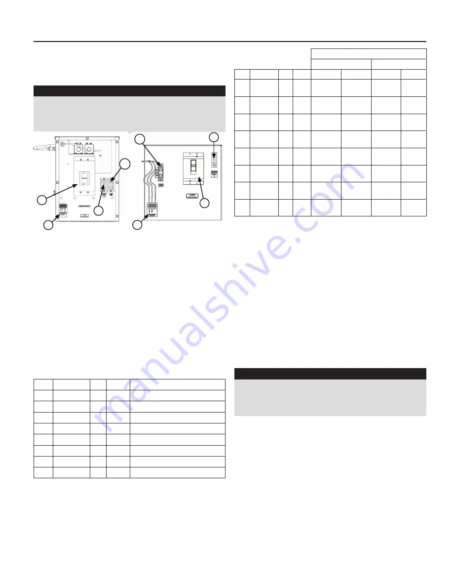
C - Ground Lug, These ground lugs are bonded to
ground and are provided for you to connect your
ground wire from the transfer switch to. The lugs on
the 60kW will accommodate #1 AWG to 250 MCM and
should be torqued to 250 in. lbs. The lugs on the 90kW
will accommodate #1 AWG to 300 MCM and should be
torqued to 250 in. lbs.
D. 120 Volt Terminal Block. These terminals are for shore
power. For a power line with one lead, plug into either
terminals, ensuring the jumper is still connected. To isolate
two leads for use of two separate circuit breakers, the
jumper must be removed.
WARNING: EQUIPMENT DAMAGE
When installing a three-phase 240 Volt system, be sure
you know which lead is the high voltage “wild” leg (208
Volt to neutral). The generator normally carriers the high
voltage on the G2 lead.
The load current carrying wires (L) and (T) must be sized
to handle the maximum load current without excessive
voltage drop. By code, the wire must be heavy enough to
handle the full current rating of the mainline circuit breaker
(or fuse) in the entrance (or sub-panel) protecting the
contactor switch.
All wires should be installed in rigid or flexible conduit.
(knockouts are provided in the control box).
GROUNDING
A grounding lug has been provided on the engine
generator set. Check your local codes for proper grounding
requirements.
NOTICE:
CLASS 1 WIRING METHODS ARE TO BE USED FOR ALL
FIELD WIRING CONNECTIONS TO TERMINAL OF A CLASS
2 CIRCUIT.
WARNING
A mainline circuit breaker has been provided inside the
generator housing. During all wiring installation, make
sure the breaker is in the off position and the generator
operators switch is in the off position.
A - Neutral Lugs, These neutral lugs are isolated from
ground and provided for you to connect your neutral wire
from the transfer switch. The lugs on the 60 kW will handle
wire sizes #4 AWG to 300 MCM and should be torqued to
250 in lbs. The lugs on the 90 kW will accommodate #1
AWG to 600 MCM and should be torqued to 300 in lbs.
B - Generator Circuit Breaker, This circuit breaker provides
overload protection for the generator. Your power feeds
from the transfer switch will connect to the bottom lugs on
the circuit breaker. The generator power feeds have already
been wired into the upper lugs.
The table below gives you the circuit breaker size, lug wire
sizes and torque specification. (see the actual breaker for
additional information and restrictions)
kW
Volts
PH Amp
Wire Capability
60
120/240
1
250
#1 AWG-600 MCM
60
120/208
3
200
#4 AWG-300 MCM
60
120/240
3
175
#4 AWG-300 MCM
60
277/480
3
90
#14 - #3/0 AWG
90
120/240
1
400
#1 AWG-600 MCM
90
120/208
3
300
#1 AWG-600 MCM
90
120/240
3
300
#1 AWG-600 MCM
90
277/480
3
150
#14 - #30 AWG
The following table shows the minimum conductor sizes
between the generator and the ATS, based on wire type
and temperature rating. Wire has been derated 40° C
ambient temperatures.
A
C
B
D
PSS60 CB PANEL
A
C
B
D
PSS90 CB PANEL
AC ELECTRICAL CONNECTIONS


