31
2.
For the Installer
2.4.16 Wood gasification boiler: mains connection and sensor installation
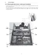
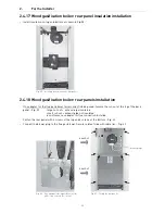
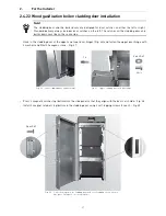
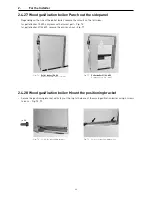
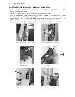
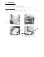
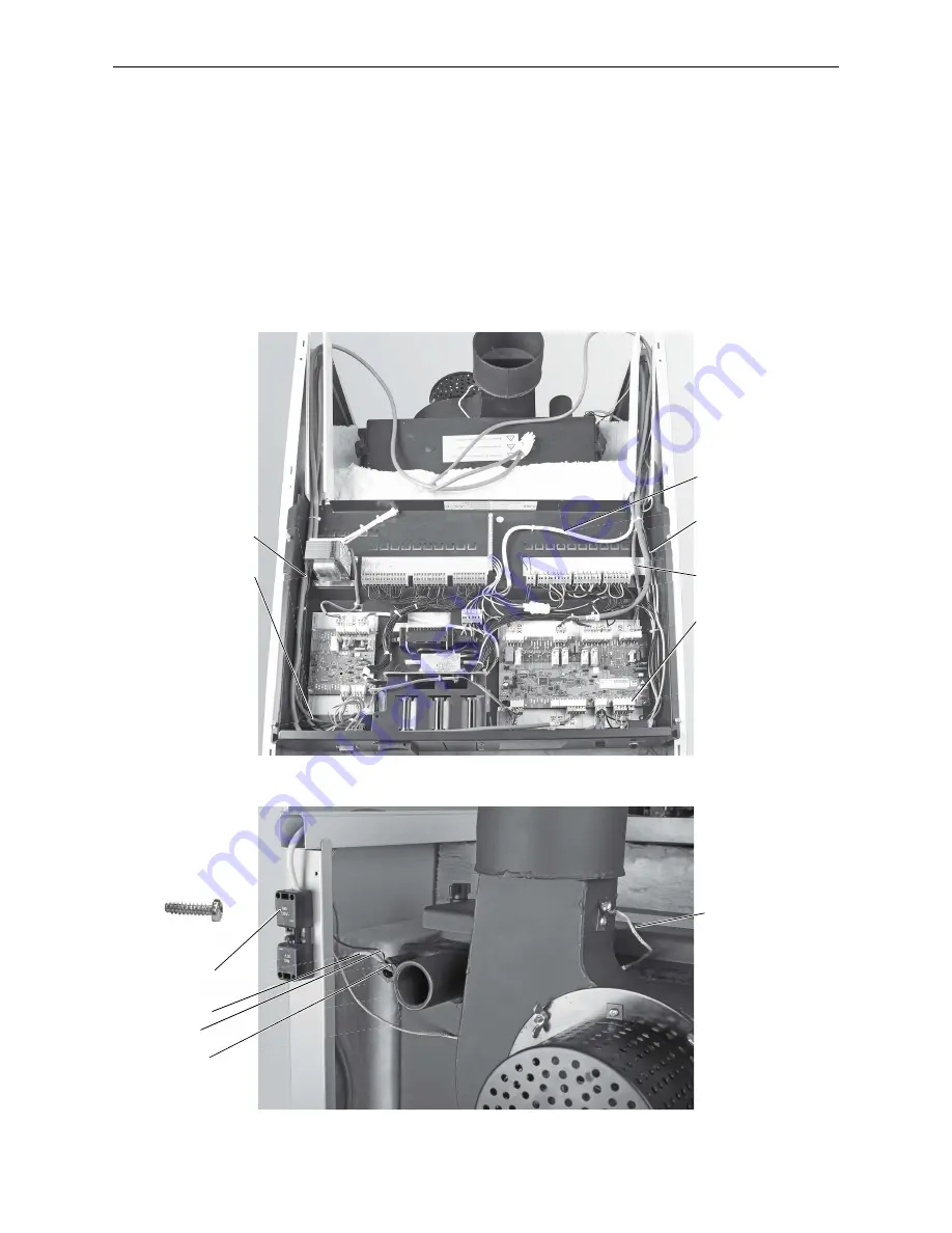
– Route the mains cable and sensor lines toward the back in the right cable channel – Fig. 51. Plug the flue gas
sensor (accessories) in the control panel to Plug X11 and also route it toward the back in the right cable chan-
nel. Route all sensor lines downward through the feed-through in the cable channel.
– Screw the power socket to the rear of the side panel with two 2.9x16 self-tapping screws – Fig. 52.
– Insert boiler sensor and safety temperature limiter sensor (STB) as far as possible into the immersion sleeve
and secure them with the sensor guard to prevent them from slipping out – Fig. 52.
– Install the flue gas sensor with protective tube (accessories) into the flue outlet, as described in the installation
instructions – Fig. 52.
– Route both cables for the flue gas blower toward the back in the cable channel – Fig. 51.
Fig. 51 Control panel, cable routing
Cable with
power plug
Boiler sensor and
STB sensor
Cable from flue gas blower
Flue gas sensor
(accessories)
Plug X11
Fig. 52 Wood gasification boiler – rear side
Power socket
Boiler sensor
STB sensor
Sensor guard
Exhaust gas sensor
with protective tube
(accessories)
Cable from flue gas blower
Cable from lambda sensor
pow
Plu
nso
r
ard
nsor
2 x
Summary of Contents for DuoWIN
Page 15: ...15 2 For the Installer ...
Page 69: ...69 5 Technical Data ...

