background image


53 


Operation types 

Motor lines and motor groups 
They can be operated 

absolutely

 (percentage of full open) or 

relatively


on the keypad ‘open/stop/close’ showed on the touch 

screen. 


Smoke zones 
They can be operated in ‘

Alarm’


or ‘

Reset’ 


Example 


Manual operation of a motor line 

If ’All’ is selected all the actuators are operated simultaneously. 

If a motor line number is selected only the selected motor line is operated. 


Motor line 

– overview 

One motor line is selected 

Manual operation on the touch screen 

17 

Configuration missing 

– main menu 

If any components, motor lines, motor groups or smoke zones are not configured they are listed here. 


If you are logged into access level 3 it is also possible to configure from this menu. 

18 

Hardware error 

– main menu 

If there are any hardware error on the panel, they will be displayed here. 
E.g. if the motor lines are not configured, the main supply is cut of, the back-up batteries are not connected, the type of weather 
station is not selected etc. 


If you are logged into access level 3 it is also possible to configure from this menu. 

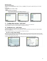
18.1 Error on the Power supply  

Mains power failure will trigger an error on the “Power supply”. Within the first minut after the failure has been detected, the green 
LED in the break glass unit will start to blink. After 30 minutes (parameter setting), the error is indicated on the touch screen and the 
windows will open (if this has been specified).    
 
Futhermore, n

on connected, wrong connected or ”dead” batteries can trigger an error on the ”Power supply”.


Error on the power supply 


Error on the Battery status 


Summary of Contents for CompactSmoke WSC 310

Page 1: ...r 2015 2017 WindowMaster is a registred trademark used under the license by WindowMaster International A S WindowMaster International A S Skelstedet 13 DK 2950 Vedb k WSC 310 WSC 320 Plus versions Ins...

Page 2: ...ions between cards 17 10 4 Main control card WCA 3SP Plus Version 17 10 5 Motor line card WCA 3M8 28 10 6 Keypad card WCA 3KI 29 10 7 Fieldbus cards 29 11 Cable monitoring of actuators 30 11 1 Usage o...

Page 3: ...oning and test run 55 21 1 The control ventilation panel is completely installed without the operating voltage applied 55 21 2 With mains voltage without accumulator 55 21 3 With mains voltage with ac...

Page 4: ...derable damage to assets The connection of the smoke ventilation panel is reserved for qualified personnel Disconnect all poles of the panel from the back up batteries prior to installation or assembl...

Page 5: ...cards may only be done when there is no power on the panel no battery or power on Motor line and input cards are ordered together with the panel and mounted to the panel from the factory side whereas...

Page 6: ...a panel with motor line card System example with WSC 320 Smoke ventilation panel 20A motor line and keypad card configured in 2 smoke zones The keypads and smoke detector units are cabled directly to...

Page 7: ...tors MotorLink actuators 24V actuators MotorLink actuators 24V actuators MotorLink actuators 2 motor lines 2 motor lines 10 motor lines WMS 306 1 10 4 10 8 20 8 20 WMS 306 2 10 2 10 4 20 4 20 WMS 306...

Page 8: ...s and spare parts Accessories Fieldbus card with field bus interface for KNX incl cover sold separately not factory mounted WCA 3FK Fieldbus card with field bus interface for BACnet MSTP incl cover so...

Page 9: ...rsion WCA 301 Fieldbus card with fieldbus interface for KNX incl cover WCA 3FK Fieldbus card with fieldbus interface for BACnet MSTP incl cover WCA 3FM Lock cylinder incl 2 keys for WSC 310 320 panel...

Page 10: ...easuring LED message OK fault and alarm Green Yellow Red all OK fault fire Reopening the actuators Every 2 min in 30min after a SHE open selectable Pre set no reopening Connection cable Actuators Othe...

Page 11: ...is instruction However this has to be agreed with the Engineer or if necessary with the local fire protection department Do not reduce the cable cross sections specified in the cable lengths table All...

Page 12: ...NYM concealed can be used For surface laying halogen free safety cables are recommended see cable plan If possible the use of cable types should be agreed with the Technical Services and the competen...

Page 13: ...3 wire 4 00 mm 1A 42m 84m 168m 140m 280m 224m 2A 21m 42m 84m 70m 140m 112m 3A 14m 28m 56m 47m 93m 75m 4A 11m 21m 42m 35m 70m 56m 5A 8m 17m 34m 28m 56m 45m 6A 7m 14m 28m 23m 47m 37m 7A 6m 12m 24m 20m 4...

Page 14: ...oss section a Total actuator current I 3 wire 0 75mm 3 wire 1 50 mm 5 wire 1 50 mm 2 wire parallel 3 wire 2 50 mm 5 wire 2 50 mm 2 wire parallel 3 wire 4 00 mm 1A 42m 50m 2A 21m 40m 50m 3A 14m 28m 50m...

Page 15: ...panel where the power supply unit is located in the left side of the panel wherefrom also mains is pulled The power supply unit for the WSC 320 panel is located underneath the main control and motor...

Page 16: ...e physical design of the panel inside the cabinet and thereby eg where mains is connected to the main control board WCA 3SP 10 1 WSC 310 mains connection and power supply unit WCA 3P1 WSC 310 WCA 3P1...

Page 17: ...ak glass units 1 input for smoke detector 1 input for 24V 48V Output for fault signal to Fire Alarm System Input for weather station incl wind direction WLA 330 331 340 WOW 201 202 Input for master sl...

Page 18: ...me type Connection cable diameter flexible max 6 mm solid max 10 mm Cable length see the chapter Cable dimensioning If cable monitoring is wanted an end of line motor module type WSA 510 must be added...

Page 19: ...Input 1 3 1 input 1 1 3 2 input 1 2 3 3 GND 1 0V Input 2 4 1 input 2 1 4 2 input 2 2 4 3 GND 2 0V Fire Alarm System shown with cable monitoring type 1 and type 2 Cable monitoring Type 1 Type 1 is use...

Page 20: ...ss unit bus 1 respectively to break glass unit bus 2 It is optional if they are connected in a ring 3 or more smoke zones break glass units are always to be connected in a ring Break glass units conne...

Page 21: ...connection to WSC 3xx for cable types and lengths Connection of different types of smoke detectors to CompactSmoke Smoke detector type WSA 300 Hekatron MSD 523 max 5 pcs Hekatron SSD 521 a WSA 200 61...

Page 22: ...1V Max 50V Connection example X9 Solid state outputs one solid state output for transmission of fault signal to Fire Alarm System and 2 free configurable Data 9 1 Fault Open contact Fault closed conta...

Page 23: ...LA 330 or WLA 340 rain sensor WLA 331 Or connection of intelligent weather station wind direction dependent smoke and heat extraction e g wind speed sensor WOW 201 wind direction sensor WOW 202 juncti...

Page 24: ...ors WLA 330 and WLA 331 the settings of the sensors are set on the sensor WLA 340 the settings of the sensor are programmable on the smoke panels touch screen Data 10 1 24V UPS 10 2 Wind speed 10 3 GN...

Page 25: ...aust ventilation intelligent weather station Data 10 1 24V UPS 10 2 Wind speed Direction 10 3 GND 0V 10 4 24V 10 5 Rain 10 6 GND 0V As the weather station is monitored by both communication and time o...

Page 26: ...sed for the connection On the slave panel the connection is done via X11 It is possible to connect several panels in a master slave connection However the max total number of panels AND break glass un...

Page 27: ...nels only responds to commands received from the master panel the response time in example 2 is heavily increased in comparison with the response time in example 1 J1 Connection for power supply J2 Po...

Page 28: ...A 3SP X1 X8 For connection of 24 Standard actuators or MotorLink actuators Data x 1 24V 0V x 2 Cable monitoring Communication x 3 0V 24V For actuator connections please see explanation in section WCA...

Page 29: ...t IP interface The connection of a fieldbus card enables communication and access to the available bus objects depending on the chosen system Smoke extraction function has always higher priority than...

Page 30: ...10k resistors simple WSA 510 monitors for interruption on the entire cable Works with all WindowMaster actuators and most non WindowMaster actuators 11 1 Usage of non WindowMaster actuators When using...

Page 31: ...touch screen has a help function with text explaining the menu item The help text occurs when the menu item is pressed text on white background For displaying the help text press the item e g Motor t...

Page 32: ...e access to the access level is open the touch screen in on see section 0 Log in To configure a sub menu press the light blue number field enter value the number of the motor line change factory setti...

Page 33: ...tors outputs on the main control card as well as the eight actuators outputs on the motor line card if such is connected are to be configured Motor lines with actuators connected are to be configured...

Page 34: ...motors displayed if actuator type MotorLink 3 Motor group 4 Expected no of locking motors 4 1 No of found locking motors see appendix 5 Manual speed 6 Auto speed 7 Manual command auto off period 8 Re...

Page 35: ...igured in 1 Controlling smoke zones 2 Comfort open position 3 Comfort open close time 4 Use safety from smoke zone 5 Wind directions where to close during alarm The appendix contains all the items tha...

Page 36: ...ts Note The break glass unit must be set in ring and the setting to Yes to have the error indication on the All group field on the overview of the break glass units Break glass unit configuration Over...

Page 37: ...g limits of the windows when alarm is triggered Smoke zones configuration Overview Smoke zones Overview Smoke zones The smoke zone are to be configured in Configuration of All All 1 High temp target s...

Page 38: ...s selected the chosen function s will be reset Number of smoke detectors to give an alarm If it is selected that the alarm is only triggered when more smoke detectors give alarm the smoke detectors ar...

Page 39: ...s of the local and Master safety signal are shown Used to associate Master Safety signal to Motor groups Local inputs are to be configured in Configuration of local input on X7 Input X7 on WCA 3SP smo...

Page 40: ...trol smoke zones 2 1 Function in controlled smoke zones displayed only if Control smoke zones is selected 3 Active state The appendix contains all the items that can be configured see appendix for det...

Page 41: ...red in Configure the input with Comfort safety as Function in controlled smoke zones 1 Configure the motor groups to Use safety from smoke zone Yes 2 Configure if needed also the motor groups in the s...

Page 42: ...ocal output shall be configured in Configuration of a local output shown for S1 X9 3 4 1 Output type informs the type Binary output is not to be configured 2 Output mode 2 1 Controlled by smoke zones...

Page 43: ...the panels to share weather data The panel with the connected weather station will be the master The first time a slave panel discovers a master panel the WSK Link Master present will become true In t...

Page 44: ...tepless variable For 24 Volt motor lines 0 or 100 2 Sequential control with upon what should the motor line wait 1 Motor line 2 Local input 3 The state of a KNX object 4 The state of a BACnet object 3...

Page 45: ...ones The master slave connection between two panels is done via input X5 or X6 on the master panel the input also used for connection to a break glass unit and input X11 on the slave panel A smoke pan...

Page 46: ...with a smoke should not react to safety signals you have to configure the motor group with Use Safety from Smoke zone No Select From WSK Link in the Weather Sensor type menu to be able to use wind sp...

Page 47: ...nd the master s own connected components are treated on equal terms To get the fastest response it is recommended that break glass units are connected to the master 14 12 Network For configuring netwo...

Page 48: ...iguration You can open the panel house and operate the touch screen for showing status manual operating of the windows as well as configuration and changing the pre set values All the menus and sub me...

Page 49: ...as documentation It is also possible to reinstall from the USB stick Files on the USB stick can be printed from a computer Configuration Configuration files on USB overview Configuration files on USB...

Page 50: ...tification can be activated or deactivated Message when the service timer expires When the service timer expires the touch screen will show a maintenance text and a clear beeping will sound from the p...

Page 51: ...ferent priority and MotorLink motor speed Fieldbus link Conn 1 10 The KNX or BACnet has also 10 configurable binary communication objects These can either be used for sending comfort commands to one o...

Page 52: ...all the menu items that can be configured under Configuration as well as e g the status of the power supply including mains and battery status and slots inform the type of card in the slot Main overvi...

Page 53: ...possible to configure from this menu 18 Hardware error main menu If there are any hardware error on the panel they will be displayed here E g if the motor lines are not configured the main supply is c...

Page 54: ...evel 3 it is also possible to configure from this menu It is possible to view all details for Motor line Motor group Break glass unit Smoke zone Local input Local output Weather Power supply Network S...

Page 55: ...oor contact on the break glass unit is pressed We recommend that the software of the panel is updated during the annual maintenance check We recommend that the commissioning of the smoke panel should...

Page 56: ...a Disconnect the mains power See also national guidelines b When a mains error have occurred the green LED in the break glass units will flash for 30 minutes The green LED on the WCA 3SP card in the s...

Page 57: ...22 2 Replacement cards 22 2 1 Replacement of 3M8 and 3KI cards 1 Disconnect the 230 V and the batteries 2 Wait until the display has completely turned off before removing the card 3 Insert the replace...

Reviews: