Enterprise Gateway
Doc No. A3930_UM Rev 2
7
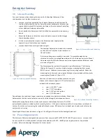
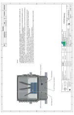
To prevent damage during shipping, the router and antennas are packaged separately, and
therefore need to be attached on-site. To complete the on-site assembly, a Phillips head
screwdriver is needed. Refer to the photo in Figure 2-1 for reference and use the parts
listed in Table 3-1.
3.4
Installation Overview
1)
If the Gateway install is part of a new online system commissioning, ensure asset
is both de-energized and locked out/tagged out per facility’s standard procedures.
Adhere to all safety procedures required by the facility and acquire all necessary
work permits.
2)
Choose Gateway mounting location. For details, see
Important: Gateway location is central to all Controllers in vicinity.
3)
Drill holes at Gateway mounting location. If using aluminum mounting bars
AND
wall thickness is larger than 0.125”, customer must supply four 1/4”-20 screws
longer than supplied in the Windrock kit (1/4-20 x 1”).
4)
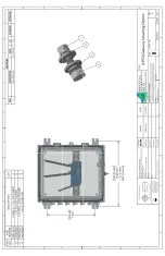
Assemble Gateway. Install router on DIN rail and mount feet on bottom of enclosure. Mounting Option #1 or
Mounting Option #2 (
) are both fastened to the enclosure using the flat head screws included in the OEM
foot kit and a Phillips head screwdriver.
5)
Mount A3930 Gateway unit. If using the aluminum mounting bars, attach using 1/4”-20 screws, lock washers, and
nuts provided with the system. If using the plastic mounting feet, provide #10 screws (
supplied by customer
).
6)
Customer must provide supply voltage at desired mounting location. For details, see
Section 3.6
and the Spotlight
Datasheet
.
Ensure power is de-energized.
7)
Install disconnecting device, clearly marked (
supplied by customer
).
8)
Attach
WiFi
antenna to Gateway. Orient direction of antenna according to Figure 2-1.
NOTE: Hold the antenna
steady in position shown while screw-mounting the connection. Improper technique can damage the
antenna
9)
Attach both Cellular LTE antennas to
DIV
and
ANT
connections on router
.
Orient direction of antennas according to
Figure 2-1.
NOTE: Hold the antenna steady in position shown while screw-mounting the connection.
Improper technique can damage the antennas
.
10)
Connect internal power cable to router
PWR
.
11)
Connect Ethernet cable to router
ETH1
connector.
12)
Connect 24Vdc integral power cable to disconnecting device.
a.
White conductor is positive.
b.
Black conductor is ground return.
13)
Energize A3930 Gateway unit. Once powered on, the Gateway needs time to boot and automatically configure the
WiFi and connect to the cellular network. This may take as long as 30 to 40 minutes.
14)
To verify entire system operation, please call (865) 330-1100 and ask for Spotlight Installation Support.
15)
Once configured, it is not necessary to interact with the system locally as its status and operation can be observed
within the Cloud and accessed from Windrock Enterprise and downloaded to Windrock MD.
Description
Qty
WiFi antenna
1
4G LTE antenna
2
Router
1
Gateway Enclosure
1
Aluminum Mounting Bars
(Mounting Option #1)
2
OEM foot kit
(Mounting Option #2)
1
Table 3-1, On-site Assembly Parts

