Enterprise Gateway
Doc No. A3930_UM Rev 2
8
3.5
Gateway Mounting
Care must be taken when choosing the location for the Spotlight Gateway. A few
considerations must be taken into account:
a.
Location is within unobstructed line-of-sight of Gateway, ideally less than 50
feet from the furthest Controller. Communications over greater distances may
require that directional WiFi antennas be fitted to the more distant Controllers,
or that additional Gateways be installed.
b.
Do not position the Gateway so that it is difficult to operate the disconnecting
device.
c.
Mount the Gateway such that the router indicators are easily visible through
the windowed enclosure.
d.
In order to provide reliable uptime, the Gateway power supply must be
separate from all Controller power supplies.
e.
Location should have a strong cell phone signal.
The Spotlight Gateway is intended to be mounted
on the exterior of any sheet metal enclosure or
flat wall surface.
Prior to mounting, some assembly is required. To prevent damage during
shipment, the router is packaged separately within the Gateway enclosure. Mount
the router onto the DIN rail and reconnect internal power cable and Ethernet cable
as shown in Figure 2-1.
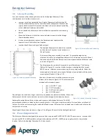
The Gateway can be structurally mounted in two different ways. The first way
(Option # 1, Figure 3-2) uses two slotted aluminum mounting bars that accept
#10-32 screws. Windrock recommends using this mounting method. Attach the
mounting bars to the enclosure using the flathead screws included with the plastic
mounting feet (Option # 2, Figure 3-3).
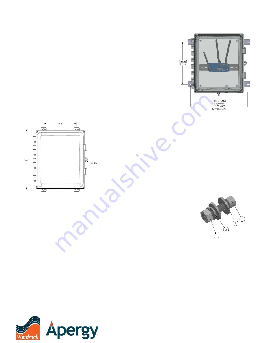
Once done, the enclosure should be mounted using the
fastener stack shown in Figure 3-4. These fasteners are
included with a standard system:
•
Item 1, 1/4-20 X 1” screw
•
Item 2, 1/4" flat washer
•
Item 3, 1/4" split lock washer
•
Item 4, 1/4-20 hex nut
Depending on site conditions, longer screws may be needed to complete installation. Mount the
Gateway such that the router indicators are easily visible through the windowed enclosure.
Gateway Mounting Option #2 can also be used to secure the Gateway Enclosure. The OEM
polycarbonate enclosure includes a plastic mounting foot kit. If this option is better suited for the installation, install each of
the four feet to the enclosure using the included flat head screws. #10 screws (not included) must then be used to fasten the
enclosure to a structure.
Mounting hole dimensions are shown in Figure 3-2 and Figure 3-3 as well as the Spotlight Datasheet.
3.6
Power Requirements
The Enterprise Gateway is designed to be powered from an approved SELV LPS 10VDC – 60VDC power source. Locations that
do not have 10VDC – 60VDC available will require the addition of 10VDC – 60VDC power supplies rated for the installed
location. Refer to the Spotlight Datasheet for further details.
Figure 3-2, Gateway Option #1 Mounting
Figure 3-4, Option # 1 Mounting Fasteners
Figure 3-3, Gateway Option #2 Mounting

