background image

Page 9

For technical questions, please call 1-888-866-5797.

Item 62603 


SAFET

y

Op

ERA

TION

M

AINTENAN

c

E

SETU

p

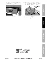
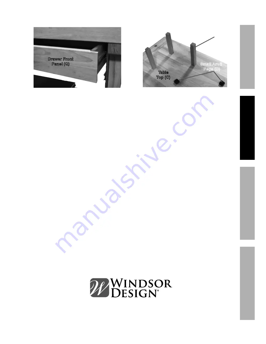
21. Slide Drawers into tracks along Sliding Partition 

and insides of the Legs.  See Figure 17, below.

Drawer Front  

panel (Q) 

Figure 17

22. Once all Drawers are inserted, tap Wood Pegs 

(B) and Small Anvil Pegs (D) into desired holes 

on the Table Top.  See Figure 18, below.

Wood pegs (B) 

Small Anvil 

 pegs (D) 

Table  

Top (c) 

Figure 18

The Workbench is now fully 

assembled and ready for use.

Summary of Contents for 62603

Page 1: ...nce When unpacking make sure that the product is intact and undamaged If any parts are missing or broken please call 1 888 866 5797 as soon as possible Copyright 2015 by Harbor Freight Tools All rights reserved No portion of this manual or any artwork contained herein may be reproduced in any shape or form without the express written consent of Harbor Freight Tools Diagrams within this manual may ...

Page 2: ...rt symbol It is used to alert you to potential personal injury hazards Obey all safety messages that follow this symbol to avoid possible injury or death Indicates a hazardous situation which if not avoided will result in death or serious injury Indicates a hazardous situation which if not avoided could result in death or serious injury Indicates a hazardous situation which if not avoided could re...

Page 3: ...load on Table to avoid tipping 3 Use as intended only Do not use Workbench to perform task for which it was not designed 4 For indoor use only 5 Assemble only according to these instructions Improper assembly can create hazards 6 Wear ANSI approved safety goggles and heavy duty work gloves during assembly and use 7 Keep assembly area clean and well lit 8 Keep bystanders out of the area during asse...

Page 4: ... please call 1 888 866 5797 Item 62603 Safety Operation Maintenance Setup Specifications Top Shelf Weight Capacity 250 lb Drawer Weight Capacity 25 lb per drawer Bottom Shelf Capacity 200 lb Vise Capacity 7 Table Top Thickness 2 1 2 ...

Page 5: ...ill allow the Bolts to be threaded into the Cross Brace See Figure 1 below Connecting Nuts K Leg A L A R Cross Brace F Figure 1 2 Set the Cross Brace against a Leg A L and use the Hex Key M and Bolt K to fasten the Cross Brace and Leg together See Figure 2 below Cross Brace F Leg A L A R Hex Key M Figure 2 NOTE Make sure the groove in the Cross Brace is facing IN 3 Repeat Step 2 for the second Leg...

Page 6: ...down on a smooth padded surface This will allow you to install the sliding drawers 9 Set the Sliding Partition P into place by inserting the tabs at the end of the Partition into the holes at the center of the Table Top s underside See Figure 6 below Sliding Partition P Table Top C Figure 6 Note Verify that the Sliding Partition and Table Top face the same direction See Figure 7 below Sliding Part...

Page 7: ... Use the Hex Key and Bolts J to fasten the tops of the Legs to the Table Top underside three Bolts per side See Figure 10 below Table Top C Leg A L A R Bolt J Figure 10 13 With assistance set the assembled frame right side up where desired 14 Remove the Vise Screw and Washer V from the middle thread of the Vise E See Figure 11 below Vise E Vise Screw Washer V Figure 11 15 Once the Vise Screw and W...

Page 8: ...en the Drawer Panel Q and the Drawer Slot Panel S L S R to the Drawer Front Panel See Figure 14 below Drawer Front Panel Q Drawer Slot Panel S L S R Screwdriver Figure 14 19 Slide the Drawer Bottom T into the grooves along the insides of the side panels making sure the felt side is up then fasten the Drawer Back Panel to the ends of the two side Panels See Figure 15 below Drawer Bottom T Drawer Sl...

Page 9: ...along Sliding Partition and insides of the Legs See Figure 17 below Drawer Front Panel Q Figure 17 22 Once all Drawers are inserted tap Wood Pegs B and Small Anvil Pegs D into desired holes on the Table Top See Figure 18 below Wood Pegs B Small Anvil Pegs D Table Top C Figure 18 The Workbench is now fully assembled and ready for use ...

Page 10: ... and Diagram PLEASE READ THE FOLLOWING CAREFULLY THE MANUFACTURER AND OR DISTRIBUTOR HAS PROVIDED THE PARTS LIST AND ASSEMBLY DIAGRAM IN THIS MANUAL AS A REFERENCE TOOL ONLY NEITHER THE MANUFACTURER OR DISTRIBUTOR MAKES ANY REPRESENTATION OR WARRANTY OF ANY KIND TO THE BUYER THAT HE OR SHE IS QUALIFIED TO MAKE ANY REPAIRS TO THE PRODUCT OR THAT HE OR SHE IS QUALIFIED TO REPLACE ANY PARTS OF THE PR...

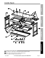
Page 11: ...eration Maintenance Setup Assembly Diagram Record Product s Serial Number Here Note If product has no serial number record month and year of purchase instead Note Some parts are listed and shown for illustration purposes only and are not available individually as replacement parts ...

Page 12: ...so the above limitation of exclusion may not apply to you THIS WARRANTY IS EXPRESSLY IN LIEU OF ALL OTHER WARRANTIES EXPRESS OR IMPLIED INCLUDING THE WARRANTIES OF MERCHANTABILITY AND FITNESS To take advantage of this warranty the product or part must be returned to us with transportation charges prepaid Proof of purchase date and an explanation of the complaint must accompany the merchandise If o...

Reviews: