background image

CONTROLS 

 SGJ32  86037680  01/03/07 

  3-12 


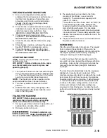
11. BRAKE PEDAL 
 

The brake pedal is located on the floor to the right side of the steering column pedestal.  The pedal operates 
the disc brake on the drive wheel.  To slow or stop the vehicle, apply pressure to the brake pedal. 


12. PARKING BRAKE LEVER 
 

The black knob located on the right side of the steering column pedestal is used to set the parking brake.  To 
set the parking brake, fully depress the brake pedal and push the parking brake knob.  To release the parking 
brake, fully depress the brake pedal.  Then release pressure on the brake pedal.  The parking brake knob will 
return it to its’ released position. 

FOR SAFETY: Before leaving or servicing machine; stop on level surface, set parking brake, turn off 
machine and remove key. 


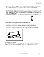
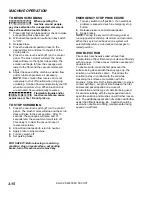
13.  DIRECTIONAL CONTROL PEDAL AND SPEED REDUCTION FEATURE 
 

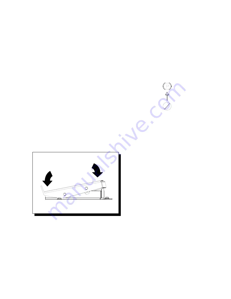
This pedal controls the direction of travel and the speed of the vehicle. Slowly pressing the front of the pedal 
causes the machine to travel forward.  Pressing the rear of the pedal causes the vehicle to travel in reverse. 
The vehicle speed can be controlled by varying the pressure on the front or rear of the pedal. 


FOR SAFETY: The vehicle can coast for a short distance after releasing the directional pedal.  
Remove the foot from pedal and use brakes to slow or stop the machine. 


SPEED REDUCTION FEATURE 

 
Maximum speed of machine can be decreased to 80% of maximum by disconnecting wire 3 white from wire 16 
white, located between controller and LCD display.  Machine is set at 100% speed setting at factory. 


FORWARD 

REVERSE 

Summary of Contents for 1000136404

Page 1: ...PRV MODELS SGJ32 10052530 AFTER SN 1000136404 86037680 11 05 08 PRV NO 980230 N SCRUBBER Operating Instructions Read these instructions before using the machine ...

Page 2: ...______________________________ MODEL _______________________________________ DATE OF PURCHASE __________________________ SERIAL NUMBER ______________________________ SALES REPRESENTATIVE _____________________ DEALER NAME ________________________________ OPERATIONS GUIDE NUMBER ___________________ PUBLISHED __________________________________________ OVERVIEW The Saber Glide is a battery powered rid...

Page 3: ...gee Blade 4 6 Side Squeegee 4 7 Replace Rotate Side Squeegee Blades 4 7 Adjusting the Side Squeegee Deflection 4 7 Scrub Brush Replacement 4 8 Brake 4 9 Steering Chain Tensioner 4 9 Vacuum Motor 4 10 Brush Motor 4 11 Traction Motor 4 12 Fuse 4 12 Circuit Breakers 4 12 Squeegee Actuator 4 13 Scrub Deck Actuator 4 14 Transporting Machine 4 15 Jacking Machine 4 16 Service Schedule 4 17 Machine Troubl...

Page 4: ...ion contains assembled parts illustrations and corresponding parts list The parts lists include a number of columns of information REF column refers to the reference number on the parts illustration PART NO column lists the part number for the part PRV NO reference number QTY column lists the quantity of the part used in that area of the machine DESCRIPTION column is a brief description of the par...

Page 5: ...mercial use for example in hotels schools hospitals factories shops and offices for more than normal housekeeping purposes Maintenance and repairs must be done by qualified personnel If foam or liquid comes out of machine switch off immediately Disconnect battery before cleaning or servicing Before the machine is discarded the batteries must be removed and properly disposed of Make sure all warnin...

Page 6: ...s information carefully Know when these conditions can exist Locate all safety devices on the machine Please take the necessary steps to train the machine operating personnel FOR SAFETY DO NOT OPERATE MACHINE Unless Trained and Authorized Unless Operation Guide is Read and understood In Flammable or Explosive areas In areas with possible falling objects WHEN SERVICING MACHINE Avoid moving parts Do...

Page 7: ...e location of safety labels on the machine If at any time the labels become illegible promptly replace them SAFETY DECAL 86242480 PRV NO 500111 BATTERY CAUTION 86248210 PRV NO 500109 HORN DECAL 86248210 PRV NO 81349 CIRCUIT BREAKER 86244130 PRV NO 500859 BRUSH CAUTION 86242510 PRV NO 500115 BRUSH CAUTION 86242510 PRV NO 500115 ...

Page 8: ... in neutral Solution tank capacity 30 gal 115 L Recovery tank capacity 30 gal 115 L Scrub brush diameter for 32 in 81 cm disk scrub head 16 inch 40 6 cm Scrub brush pressure 0 225 lbs 0 1000N Scrub brush speed 300 rpm Tires 12 in 30 5 cm Solid Scrubber Compound Foundation Pressure 108 lbs in 745 kPa Maximum Speed 4 1 miles hour 6 5 Km hour Coverage with 32 in 81 cm scrub head 48 840 ft hr 3 7 mph ...

Page 9: ... measured to be below 2 5m s2 This was a tri axial third octave band measurement made during normal operation on a composite tile floor The measurement and related calculations were made in accordance with ANSI S3 34 1986 SPECIAL NOTES The sound pressure level at the operator s ear was measured to be 72 3 dBA This was a nearfield broad band measurement taken in a typical industrial environment on ...

Page 10: ...rities and changes in the floor without loosing contact with the floor The scrub deck skirts and side squeegees control the cleaning solution on the floor so that the squeegee can pick it up The one touch switch controls the motors and lift actuator to turn the motors on and lower the deck or turn the motors off and raise the deck The brush pressure switch controls the down pressure on the scrub d...

Page 11: ...l 2 Front cover 3 Side cover 4 Tank 5 Recovery tank cover 6 Recovery tank dome 7 Recovery tank drain hose 1 2 4 3 11 5 6 8 9 10 12 13 7 8 Scrub head 9 Scrub head side squeegee 10 Solution tank drain hose 11 Solution tank cover 12 Squeegee 13 Vacuum motor ...

Page 12: ...CONTROLS SGJ32 86037680 01 03 07 3 5 1 2 3 4 5 6 7 10 8 13 20 14 11 20 16 12 19 17 18 15 9 ...

Page 13: ...er adjustment knob 19 Squeegee deflection adjustment knob 20 Side squeegee deflection adjustment knob 1 KEY SWITCH Controls the power for the machine functions To turn the machine power on rotate key clockwise When the key is turned on the battery symbol will flash for 12 seconds while the system runs self diagnostics and returns scrub deck and squeegee to raised position if necessary The controll...

Page 14: ...will rise and the brush pressure indicator will display error code 9000 To stop scrubbing press the one touch switch The brush drive motors will turn off the scrub deck will raise the solution flow will stop the squeegee will raise after a 15 second delay and the vacuum motor will turn off This delay is to clear the vacuum hose of recovered solution 4 BRUSH PRESSURE SWITCH This switch controls the...

Page 15: ...adjust the solution flow to the scrub deck without resetting each time the scrubbing operation is interrupted If recycling option is installed this switch controls the amount of solution flow to the scrub deck by controlling the speed of the pump NOTE Press switch and hold momentarily each time to change solution flow 6 VACUUM SQUEEGEE SWITCH This switch independently controls the vacuum motor and...

Page 16: ...NFORMATION DISPLAY SCREEN 1 The hour meter is viewed on screen 2 of the information display Hours are displayed for key ON time brush run time and traction motor time INFORMATION DISPLAY SCREEN 2 Records the time spent propelling the machine and gives true traction motor time Records the entire time that the key is on Records the time spent with the brushes running and gives true brush motor time ...

Page 17: ...e left side of either information screen 1 or information screen 2 The level of battery charge is indicated by the horizontal bars in the battery meter box When the batteries require charging the icon will flash and a battery inhibit icon will appear on the right side of either information screen Scrub and solution functions that are running when the battery inhibit icon appears will be automatica...

Page 18: ...re is an adequate amount of water in recovery tank before starting recycle pump and turn off recycle pump when water level reaches filter To stop the solution recycle pump press the switch The pump will stop and the green indicator light will turn off and the solenoid valve will resume control of solution flow to the scrub deck 9 RECYCLE INDICATOR LIGHT OPTIONAL This light will turn on when the re...

Page 19: ... or servicing machine stop on level surface set parking brake turn off machine and remove key 13 DIRECTIONAL CONTROL PEDAL AND SPEED REDUCTION FEATURE This pedal controls the direction of travel and the speed of the vehicle Slowly pressing the front of the pedal causes the machine to travel forward Pressing the rear of the pedal causes the vehicle to travel in reverse The vehicle speed can be cont...

Page 20: ... in front of seat at the bottom While in a standing position grasp the back of the seat and the seat adjustment grab bar and lift seat into the adjustment slot and lower into one of the locking positions Adjust the seat to the desired position 18 SQUEEGEE CAMBER ADJUSTMENT KNOB The squeegee camber adjustment knob is located at the center of the squeegee at the rear of the machine See maintenance s...

Page 21: ...urn off machine and remove key 1 Set squeegee and scrub deck to up position set parking brake and turn off key switch 2 Remove solution tank cover Flammable materials can cause an explosion or fire Do not use flammable materials in the tanks 3 The solution tank can be filled to the FULL marking of the fill inlet Leave room for detergent The solution tank capacity is 30 gallons 114 liters The water...

Page 22: ...clear the vacuum hose of recovered solution 2 Allow directional pedal to return to neutral 3 Apply brake to stop machine 4 Turn key switch off 5 Set parking brake FOR SAFETY Before leaving or servicing machine stop on level surface set parking brake turn off machine and remove key EMERGENCY STOP PROCEDURE 1 Turn key switch to off position If an electrical problem is suspected push in emergency sto...

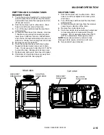
Page 23: ...es out of drain hose Do not use water hotter than 140 60 C to clean the tank Damage to tank may occur 7 Replace plug and secure drain hose in bracket 8 If machine is to be stored leave recovery tank dome open and drain hose plug off SOLUTION TANK 1 Park the machine next to a floor drain Drain hose is on left rear adjacent to recovery tank drain hose 2 Turn off the key switch and set the machine s ...

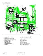
Page 24: ...queegee Adjustment 4 Scrub Brushes 5 Vacuum Filter 6 Float Switch 7 Solution Strainer 8 Brake 9 Steering Chain Tensioner 10 Vacuum Motor 11 Brush Motor 12 Traction Motor 13 Fuse 14 Circuit Breaker 15 Squeegee Lift Actuator 16 Scrub Lift Actuator 1 2 3 5 6 7 8 9 10 11 12 13 14 15 16 4 ...

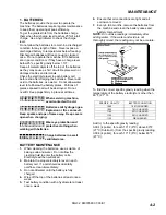
Page 25: ...ot overfill Keep plugs firmly in place at all times When servicing machine avoid contact with acid Batteries emit hydrogen gas Explosion or fire can result Keep sparks and open flame away Keep covers open when charging Wear eye protection and protective clothing when working with batteries Charge batteries in a well ventilated area BATTERY MAINTENANCE 1 When cleaning the batteries use a solution o...

Page 26: ...verflow resulting in loss of battery acid balance and damage to the machine 5 Replace battery caps and leave them in place while charging 6 Unplug the battery connector from the machine Unplug the battery charger from power outlet FOR SAFETY When charging connect the charger to the batteries before connecting the charger to the AC wall outlet Never connect the charger to the AC first Hazardous spa...

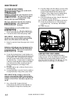
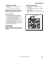
Page 27: ...tteries 7 Disconnect main positive lead and secure cable terminal away from battery batteries 8 Loosen both terminals on each jumper cable and remove one at a time 9 Prepare a suitable battery site to place batteries 10 Attach suitable battery lifting device and lift batteries from the machine Batteries are a potential environmental hazard Consult your battery supplier for safe disposal methods TO...

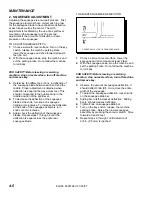
Page 28: ...the spirit level 4 To decrease the deflection of the squeegee blade at the ends turn knob on squeegee trailing arm clockwise To increase the deflection at the ends of the squeegee assembly turn knob counter clockwise 5 Again check the deflection of the squeegee blades Repeat steps 1 through 4 until the deflection is equal across the entire rear squeegee blade TO ADJUST SQUEEGEE DEFLECTION 1 Choose...

Page 29: ...osition turn off the key switch and set the parking brake FOR SAFETY Before leaving or servicing machine stop on level surface turn off machine and remove key 2 Disconnect vacuum hose and loosen the two squeegee retaining knobs 3 Pull squeegee assembly rearward from the lifting carrier 4 With squeegee assembly on bench inspect or repair as necessary 5 To reinstall align squeegee assembly to lift c...

Page 30: ...his will damage the retaining strap and deform the squeegee blade 6 Pivot the side squeegee back into place and tighten the locking knob ADJUSTING THE SIDE SQUEEGEE DEFLECTION Side squeegee should deflect approximately 3 8 in when in use If the blade is under curled it will skip low spots and leave puddles It the blade is over curled or worn it will smear water and leave stripes and streaks 1 Choo...

Page 31: ...y scrubbing and light stripping The blue pads remove less finish than brown stripping pads yet will remove black marks stains and dirt Brown Pads Stripping are used for easy and complete removal of old floor waxes finishes They will quickly remove ground in dirt black heel marks and spills When used with the proper stripper this pad leaves the floor clean and ready for finishing REPLACING OR INSTA...

Page 32: ...n of the manual The brake pedal and parking brake operate the self centering front wheel disc brake The disc and caliper should be inspected every 200hours of operation for cracks and disc wear The brake should be adjusted so that the disc pads are as close to the disc as possible without causing brakes to drag BRAKE ADJUSTMENT FOR SAFETY Before leaving or servicing machine stop on a level surface...

Page 33: ...ed extremely pitted or not concentric the motor will need to be replaced or sent to a qualified service center Important These brushes wear quicker as the length shortens due to increased heat Spring inside brush housing will damage motor if brushes are allowed to wear away completely Periodically check the length of the carbon brushes Replace both carbon brushes when either is less than 3 8 9 5mm...

Page 34: ...on motor barrel to motor cap and motor barrel to motor frame 2 Remove end cap from motor NOTE Motors contain two wave washers in cap Do not lose these 3 Release brush from spring tension Remove screw connecting brush wire lead to brush holder Clean brush holder to insure free movement 4 Install new brush and reinstall connecting screw and lead 5 When all new brushes are installed Place all in retr...

Page 35: ...screw and lead 8 When all new brushes are installed Place all in retracted position held into brush holder by spring tension 9 Carefully place end cap onto bearing on motor shaft NOTE On motors use care to assure wave washer alignment 10 With cap end in partially installed position release all brushes to contact position with motor commutator NOTE Failure to insure all brushes are released will re...

Page 36: ...axle in the lowered extended position To adjust the actuator 1 While holding actuator barrel to prevent it from spinning apply power to the actuator such that it is fully extended Positive power to white wire and negative ground to black Limit switch within actuator will stop it 2 Turn barrel out one or more full turns to assure that when it is retracted it will not bind against itself 3 While hol...

Page 37: ...olding actuator barrel to prevent it from spinning apply power to the actuator such that it is fully extended Positive power to white wire and negative ground to black Limit switch within actuator will stop it 2 Turn barrel out one or more full turns to assure that when it is retracted it will not bind against itself 3 While holding actuator barrel to prevent it from spinning apply power to the ac...

Page 38: ...ust be of the proper type and strength The combined strength of all tie downs must be strong enough to lift two times the weight of the machine Tie downs must be positioned to prevent the machine from moving forward backward or either side to side Use all four corners of the machine with the tie downs running out opposite directions Tie downs must be attached to the transporting vehicle securely P...

Page 39: ...s raised use jack stands at the designated jack locations Support the front of the machine by placing jack stands or solid wood blocks under the U shaped stabilizer bars FOR SAFETY Block machine at designated jack locations with jack stands when raised 6 Slowly lower the machine onto the jack stands 7 Be sure that the machine is secure 8 Service or inspect the machine as required 9 When finished w...

Page 40: ...m motors to dry Clean brushes or pads and check wear Clean main and side squeegee blades and check wear Clean out recovery tank and vacuum filter Clean and inspect float shutoff Clean outside of tanks check for damage Store with covers off tanks Charge batteries Check side squeegee for wear Clean off top of batteries Check battery cells with hydrometer Inspect scrub deck skirts Clean solution stra...

Page 41: ...ose brake switch connection or faulty brake switch Check connections and switch continuity Little or no propel Loose seat switch connection or faulty seat switch Check connections and switch continuity Faulty throttle Check throttle Forward speed only Reverse speed only Faulty throttle Check throttle Squeegee out of adjustment Adjust squeegee Debris caught on squeegee Remove debris Worn squeegee b...

Page 42: ...too low Turn on or increase flow setting Solution strainer plugged Clean solution strainer Solution system plumbing obstructed Clear obstruction from plumbing Solution solenoid valve obstructed or stuck Clean or replace valve Vent hole in solution tank lid obstructed Clear obstruction from vent hole Faulty solenoid valve connection Check wiring to solution valve Brush motors do not run or run slow...

Reviews: