

MAINTENANCE
4-11
GLIDE 86037550 01/09/07
!
WARNING
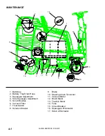
12. BRUSH MOTOR
(Refer to Brush Motor Group in parts section of
manual).
Do not use a pressure washer to clean around
the brush motors. Use tap pressure only.
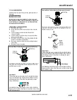
CHANGING BRUSH MOTORS
1.
With the scrub deck in the stored position,
disconnect brush motor wiring connector from
harness.
2.
Loosen side squeegee locking knob, and pivot
side squeegee away from scrub deck to access
and remove scrub brushes or pad drivers.
3.
Remove retaining bolt, lock washer, flat washer
and star drive from brush motor shaft.
4.
Remove 4 brush motor mounting bolts located
under scrub deck.
5.
Remove brush motor. If needed, lower scrub
deck for more clearance.
6.
Reverse steps to install.
BRUSH MOTOR CARBON BRUSH
REPLACEMENT
1.
Scribe alignment marks on motor barrel to motor
cap and motor barrel to motor frame.
2.
Remove end cap from motor.
NOTE: Motors contain two wave washers in
cap. Do not lose these.
3.
Release brush from spring tension. Remove
screw connecting brush wire lead to brush
holder. Clean brush holder to insure free
movement.
4.
Install new brush and reinstall connecting screw
and lead.
5.
When all new brushes are installed. Place all in
retracted position, held into brush holder by
spring tension.
6.
Carefully place end cap onto bearing on motor
shaft.
NOTE:
On motors use care to assure wave
washer alignment.
7.
With end cap in partially installed position,
release all brushes to contact position with
motor commutator.
NOTE:
Failure to insure all brushes are released
will result in motor failure.
8.
Reset end cap and realign with scribe marks on
motor barrel.
9.
Maintain alignment between motor barrel base
and cap, and between motor barrel and motor
frame. Reinstall the two attach bolts from cap
into base
Summary of Contents for 10052480
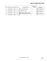
Page 48: ...CIRCUIT BREAKER GROUP GLIDE 86037550 01 09 07 5 5 1 2 3 4 ...
Page 52: ...DECAL GROUP GLIDE 86037550 01 09 07 5 9 4 2 3 6 1 5A 5B 7 8 9 ...
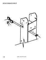
Page 54: ...FRONT BUMPER FLOOR GROUP GLIDE 86037550 01 09 07 5 11 1 4 5 6 3 2 3 7 ...
Page 58: ...SCRUB BRUSH PAD DRIVER GLIDE 86037550 01 0907 5 15 1 6 9 4 8 5 7 2B 2A 2C 3 5 2D 7 5 6 9 4 8 ...
Page 88: ...STEERING UPPER GLIDE 86037550 01 09 07 5 45 1 2 3 4 5 6A 6B 8 9 10 7 13 12 16 18 11 14 15 17 ...
Page 96: ...VACUUM GROUP GLIDE 86037550 01 09 07 5 53 3 10 1 2 4 5 7 8 6 9 8 11 12 13 ...
Page 100: ...WHEEL MOTOR SERVICE PARTS GLIDE 86037550 06 25 12 5 57 ...
Page 110: ...WIRING DRIVE MOTOR GLIDE 86037550 07 05 12 5 67 1 2 ...
Page 116: ...BACK UP ALARM OPTION GLIDE 86037550 01 09 07 5 73 1 5 3 4 2 ...
Page 118: ...DUAL VACUUM MOTOR OPTION GLIDE 86037550 01 09 07 5 75 7 6 5 4 8 9 1 3 10 11 1 2 12 1 ...
Page 120: ...WARNING LIGHT OPTION GLIDE 86037550 01 09 07 5 77 1 2 3 4 5 ...
Page 122: ...GLIDE 86037550 01 09 07 5 79 ...
Page 123: ...GLIDE 86037550 01 09 07 5 80 ...
Page 124: ...GLIDE 86037550 01 09 07 5 81 ...


