


86333220 CS20
35
Maintenance
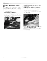
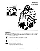
To Remove Squeegee Assembly
1. With the squeegee in the up position, turn key
switch “OFF”.
2. Disconnect vacuum hose from squeegee and
squeeze the squeegee retaining latch.
3. Pull squeegee assembly from the squeegee arm.
4. Inspect or repair as necessary and reinstall.
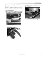
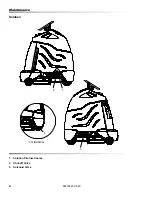
To Replace or Rotate Squeegee Blades
1. With the squeegee in the up position, turn key
switch “OFF”.
FOR SAFETY: Before leaving or servicing machine;
stop on level surface, turn off machine and remove
key.
2. Remove the squeegee assembly from the
machine.
3. Unscrew each of the four (4) knobs until they are
nearly removed from the squeegee assembly.
Grasp the squeegee assembly and push on the
knobs to remove the blade retainer.
Remove the knobs and pull the blade retainer out.
Rotate the squeegee blade to new edge position or
replace as required. Each blade has four (4) new
edge positions.
4. Pull the blades off the retainer.
To reinstall the blades, hook the blades over the
pins on the retainer plate.
5. Lower the retainer with blades back in position in
the squeegee assembly and install the knobs.
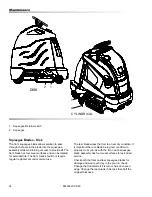
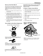
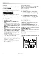
Squeegee Blades-Cylindrical
The front squeegee blade allows solution to pass
through channels in the blade into the squeegee
assembly while maintaining vacuum to provide lift. The
front blade has two (2) wear surfaces and can be
rotated for extended life. The front blade should not
require regular replacement under normal use.
The rear blade wipes the floor to a near dry condition. It
is important the rear blade be in good condition to
properly do its job. As with the front, each squeegee
blade assembly has two (2) wear surfaces for extended
service.
Check both the front and rear squeegee blades for
damage and wear each day in the pre-run check.
Change the front blade if it is torn or has an uneven
edge. Change the rear blade if it is less than half the
original thickness.
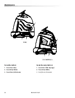
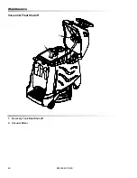
To Remove Squeegee Assembly
1. With the squeegee in the up position, turn key
switch “OFF”.
2. Disconnect vacuum hose from squeegee and
squeeze the squeegee retaining latch..
3. Pull squeegee assembly from the squeegee arm.
4. Inspect or repair as necessary and reinstall.
To Replace or Rotate Squeegee Blades
1. With the squeegee in the up position, turn key
switch “OFF”.
FOR SAFETY: Before leaving or servicing machine;
stop on level surface, turn off machine and remove
key.
2. Remove the squeegee assembly from the
machine.
3. Unscrew two yellow thumb screws. Remove
bumper wheels and plastic end caps.
4. Slide squeegee blade(s) out the end of the
squeegee.
5. Reverse procedure to install new blades.
Summary of Contents for chariot iScrub 20 CS20
Page 14: ...14 86333220 CS20 Operations Drive Controls 1 2 3 4 5 6 7 8 9 10...
Page 57: ...86333220 CS20 Parts...
Page 58: ...58 86333220 CS20 Bumper 1 2 5 6 3 4 3 7...
Page 60: ...60 86333220 CS20 Bumper Deluxe Cylindrical 1 2 5 6 3 4 3 7 5 3 4 8...
Page 66: ...66 86333220 CS20 Control Panel 2 17 9 16 3B 15 14 13 12 11 10 9 8 7 6 5 4 2 1 3A...
Page 68: ...68 86333220 CS20 Decals Disk 6 5 1 2 3 4...
Page 70: ...70 86333220 CS20 Decals Deluxe Cylindrical 2 1 3A 3A 4 3B 3B...
Page 76: ...76 86333220 CS20 Drive Mounting 1 2 3 4 5 6 7 4 7...
Page 78: ...78 86333220 CS20 Frame Rear Wheels 1 2 3 4 5 6 7 8 9...
Page 80: ...80 86333220 CS20 On Board Battery Charger Disk 6 8 1 2 15 3 4 5 6 7 9 10 11 13 14 7 6 10 12 8...
Page 84: ...84 86333220 CS20 Pedal Platform 3 4 5 6 7 8 9 10 11 1 2 2 2 2...
Page 86: ...86 86333220 CS20 Pedal Platform Mounting...
Page 90: ...90 86333220 CS20 Scrub Brush Pad Driver 8 4 9 6 5 7 5 3 2C 2A 2B 7 5 8 4 9 6 1 10A 10F...
Page 94: ...94 86333220 CS20 Scrub Brush Deck Mounting Disk 1 2 3 4 5 6...
Page 98: ...98 86333220 CS20 Scrub Deck Cylindrical...
Page 102: ...102 86333220 CS20 Scrub Brush Deck Mounting Cylindrical 1 2 3 4 8 7 6 5 9 10 11...
Page 104: ...104 86333220 CS20 Scrub Deck Lift 1 2 3 4A 5 6 7 8 12 7 10 9 11 A TORQUE 50 IN OZ A 13 4B...
Page 114: ...114 86333220 CS20 Squeegee Linkage Cylindrical 1 2 3 4 5 6 7 8 9 10 11 12 13 14 16 15 17 18 19...
Page 116: ...116 86333220 CS20 Steering 4 5B 1B 2 6B 7 1A 2 3 4 5A 6A...
Page 118: ...118 86333220 CS20 Vacuum 1 2 3 4 5 6 7 8 See maintenance section for motor mounting details...
Page 120: ...120 86333220 CS20 Wiring Battery 1A 2A 3 4 5 MAIN WIRING HARNESS 6 1B 2B...


