52
Maintenance
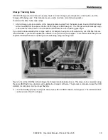
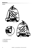
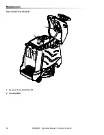
Tank Assembly Removal
In order to access the frame or drive components, the
entire tank/console cover assembly can be removed as
a single unit.
Tank Removal:
1. Open the console cover.
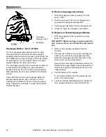
2. Tilt the recovery tank back until it stops on the
lanyard.
3. Remove the recovery tank vacuum hose from its
connection at the rear cross member.
4. Tilt the recover tank slightly forward and disconnect
the lanyard. Lean the recovery tank back until it
contacts the floor. Lift the tank and back panel from
the hinge pin and set aside.
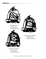
5. Disconnect the squeegee vacuum hose from the
connection at the rear cross member.
6. Grasp the lower end of the flexible steering shaft
and pull it straight up until it is disengaged with the
hex steering shaft. Place the loose end into one of
the fill ports.
7. Remove the cover and gasket at the steering shaft
area.
8. Disconnect the electrical plugs located just forward
of the battery tray. To disconnect, lift the plugs off of
their mounting plate, locate and depress the lock
tab and pull the connectors apart. Replace the
lower half of the connectors on to the support plate
after the tank assembly has been removed.
9. Remove the battery cable connection from the rear
cross member.
10. Close the console cover.
11. Locate the solution solenoid valve on the left side
of the scrub deck. Remove two electrical wires
from the valve. The wires are interchangeable. Lift
the valve out of its mount pocket and move the
valve and connected hose over to the right side of
the machine. It is not necessary to remove the
valve or hose from the solution tank.
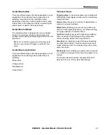
12. Remove the bumper. One mounting bolt per side is
located just above the tip pads on the inside.
13. Remove 5 bolts holding the tank in place.
14. The tank assembly can now be lifted off the
chassis and set aside.
15. Support the tank assembly so that the weight of it
is not resting on the solution valve plumbing.
16. The lower half of the electrical connectors can now
be easily placed on to their support plate.
17. Reverse the process for reassembly. Refer to the
electrical diagrams for connections.
86398220 Operators Manual - Chariot-2 iScrub 20


