COMMODORE 1
32.
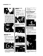
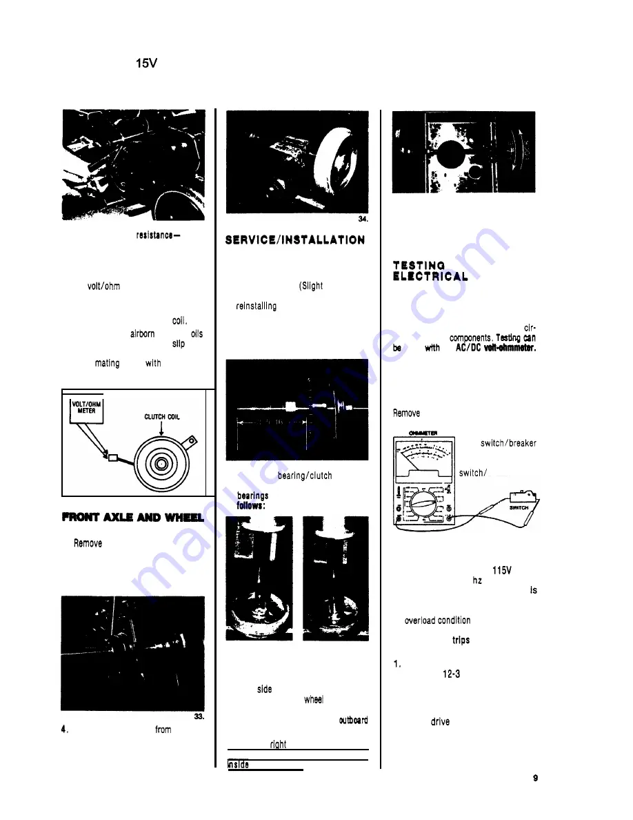
To check clutch coil
1.
Disconnect machine power cord from
2.
Disconnect clutch lead connection.
3.
Set
meter to check ohms.
4.
Connect meter leads to clutch leads.
If the meter reads below
160
ohms
or above 195 ohms replace
Accumulation of
dust and
may bause the clutch to
and
lose traction. Remove clutch and
clean
parts
a cleaning
solvent.
outlet.
ASSEMBLY REMOVAL
1.
drive chain (see Photo
28).
2.
Lay machine on side.
3.
Remove nuts and bolts holding
flange bearing to frame.
Remove axle assembly
machine
and put on workbench to service.
5.
Remove snap ring on each end of
axle
to
remove wheels.
WHEEL AND AXLE
1.
Install flange bearing on axle.
Po-
sition set screws (in locking collars)
over innermost flats on axle and
tighten screws.
adjustment
of bearings may be necessary when
assembly to frame.)
2.
When replacing sprocket on axle
note dimension
-
approximately
3
5/16
from end of axle to face of
sprocket. (Photo
33)
35.
3.
Replacing
bearings
in wheels. Thsss are directional
and must be Installed as
36.
LEFT WHEEL:
Bearing must be
pressed in from
inboard
of
wheel with knurbd
end of bearing
sleeve on Inboard
side of wheel.
37.
RIGHT
WHEEL:
Bearing must be
pressed in from
outboard side of
with knurled
end of bearing
sleeve on
side of wheel.
NOTE:
Both
and left bearing
assem-
blies must be pressed
in
flush with the
of wheel hubs.
38.
4.
To check assembly: hold axle
-
each wheel should rotate forward
freely and lock on shaft when rota-
tion is reversed.
COMMODORE
CIRCUITS:
CAUTION: Repalrs should only be at-
tempted by qualified personnel since
damage can be done by persons not
experienced
in
working with printed
cuit
boards and
done
an
SWITCHES AND
CIRCUIT
BREAKERS
them from machine and use an
ohmmeter or continuity tester. The correct
reading is zero for an
open
and infinity (conti-
nuity) for a closed
brea ker
.
BRUSH DRIVE MOTOR
This motor operates on a
60 hz
circuit
(or
230V
50
depending on
machine model). A
6
amp breaker
Installed
in the drive motor circuit
to
prevent damage to the motor in case
an
occurs.
If the breaker
after being
reset,
check for probable cause:
Incorrect power cord. Use nothing
less than
cable wire size and
no longer than
100
ft
.
2.
Brush height lever set too low. Ad-
just to correct height.
3.
Faulty
motor. Repair or re-
place as required.
4.
Brush assembly “locked-up.” Check
for obstruction
-
faulty brush bear-
ings, etc.
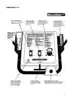
Summary of Contents for COMMODORE CMD
Page 11: ...COMMODORE 115V CONTROL PANEL ASSEMBLY I COMMOOOAE CONTROL PANEL ...
Page 12: ...2 CHASSISWIDRIVE ASSEMBLY ...
Page 14: ...COMMODORE 1 15V 14 ...
Page 16: ...COMMODORE 115V SQtUTION RECOVERY TANKS 16 ...
Page 18: ...COMMODORE 115V CONTROL PANE1 WIRING DIAGRAM 230VOLT CHASSIS WIRING DIAORAM 230 VOLT A I8 i 18 ...


