


POWER BRUSH ESCORT
(OBS)
3.
Disconnect pump motor
leads.
Disconnect
from pump
head and remove pump. Refer t o
pump drawlng
for
replacement parts.
CAUTION:
When
hose-
barbs on ump head
-
NOT
-
as
could crack
intake and discharge
in
head.
VAC SHOE
1.
Remove
(4)
bolts holding
and
pum plate to tanks. (Refer to Photos
2.
Remove
(3)
bolts hoidin
shoe/
bracket to soiutlon
Repair or
as reaulred.
NOTE
When relnstalllng a new
shoe, proper alignment
of shoe to
floor must be made.
Install
shoe and tlghten screws.
Attach chassis and pump plate as-
sembly to tank and tlghten screws.
2.
Set machine upright on a flat-level
surface (a desk top works well) and
check
shoe for level contact on
the fiat surface.
\
VAC SHOE
LEVEL
WITH
FLOOR
3.
Make adjustment at axle leveling
screws by tlghtenln
both
of the lock nuts unti? shoe Is level.
TRANSPORT WHEELS
Remove screw and hub cap and slide
wheel off axle. Before reinstalling
wheel, clean axle and apply
coating of silicone lubricant.
VAC
MOTOR EXHAUST FILTER
1.
Remove
(4
bolts holding chassis to
tanks.
to Photos
3
2.
Lay machlne on side. Pull chassis
from tanks
expose exhaust muffler.
3.
Remove hex nut from PVC muffler.
Repair or replace as required.
SWITCH CONTROL PANEL
1.
Remove (2) screws
switch
housing to handle. (EPB housing
shown)
I
SCREWS
2.
Replace switches as required.
SERVICING POWER HEAD
BRUSH
Tilt machine back to rest on handle.
2. Remove
screws holding motor and
plate t o
motor rectifier as
Page 4
of 8
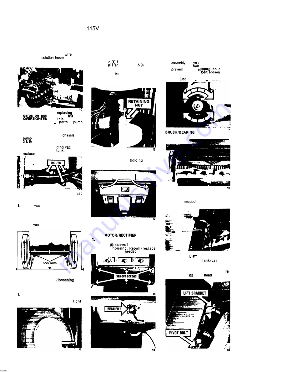
BELT ADJUSTMENT
1.
When servicing brush motor
or
brush
alwa check belt
for
proper
tension. The
should
be
taut to
it
from
on cogged
pulleys. To tighten
motor
mounting nuts and rotate motor rear-
ward
enouah to tlahten belt.
ASSEMBLY
1.
Remove belt guard.
2
Remove
screw
from each end of brush
shaft and remove brush assembly
from housing. Replace brush
or bear-
rings as
19
POWER HEAD
CABLE
I.
Remove recovery
motor
assembly.
2. Tilt machlne back to rest on handle.
Remove bolt holding cable t o
bracket and
power
pivot bolts.
4


