background image

POWER BRUSH ESCORT 115V 

(OBS) 

Page 5 of 8

3. 

pull  bracket assembly 

and remove 

pulley. 

21 

4. 

Remove pedal and bracket assernbl 
(4 screws).  Replace cable as 

22 

Reinstall  pedal  assembly  and  power 

head assembly. 

To 

adjust cabic 

Depress 

cable 

that  power  head almost touches 

shoe  houslng.  Raise  and  lower 

power  head 

pedals to  make  sure 

that  head 

“lock” 

UP  posltion 

when pedal  depressed. 
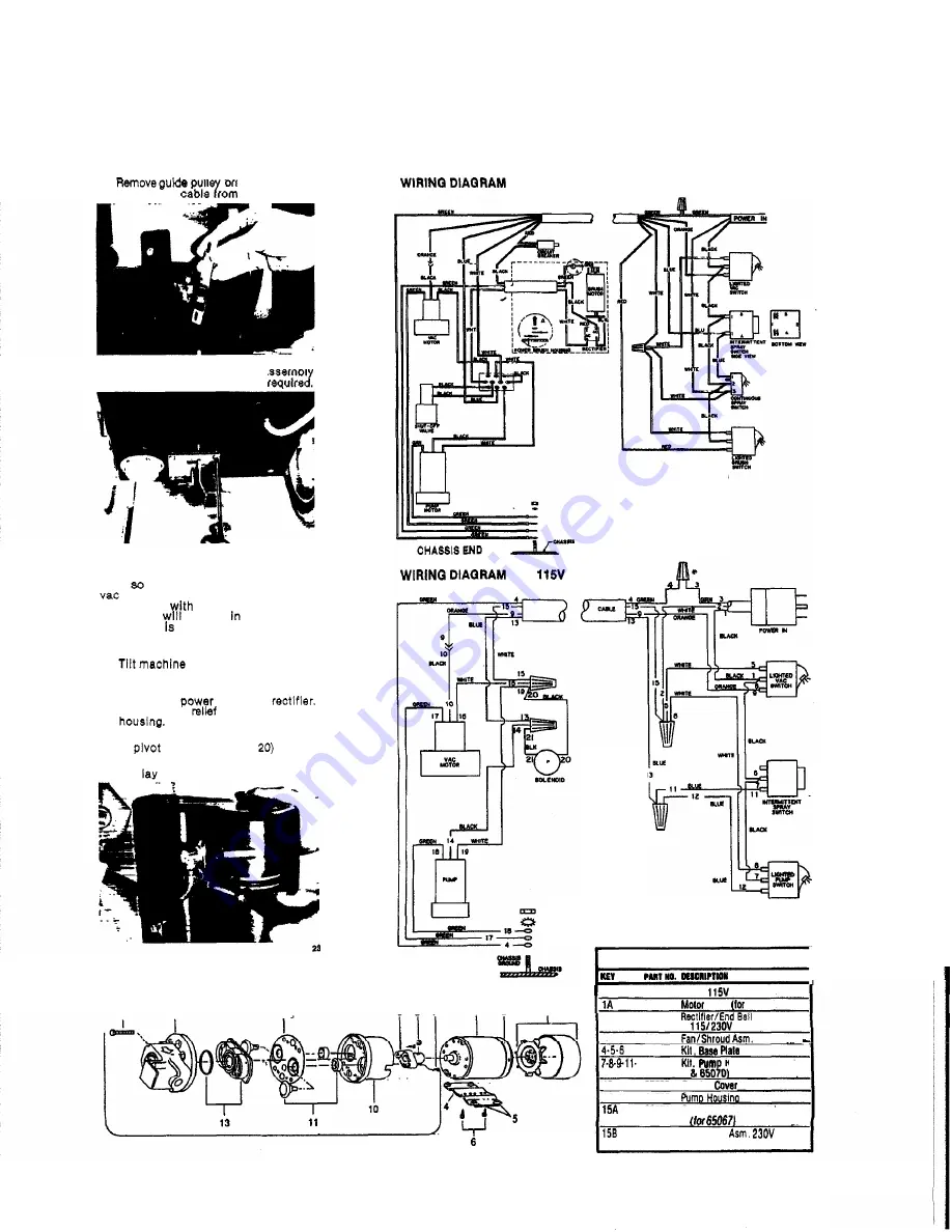
POWER HEAD 

REMOVAL 

1. 

back to rest 

on 

handle. 

Remove  brush  motor  and  plate 

assembly. 

(See 

Photo 15) 

Disconnect 

cord from 

Loosen strain 

and pull cord from 

(See 

Photo 16) 

3. 

Remove  cable from 

lift bracket and 

(2) 

bolts. (See Photo 

4.  Disconnect solution hose from elbow 

and 

head 

aside. 

PUMP ASSEMBLY 

15 

14 

12. 

EPB CHASSIS ASSEMBLY 

CONTROL PANEL END 

ESC 

CHASSIS END 

9

8

7


1

2


15 

CONTROL 

PANEL END 

PUMP PARTS 

LIST 

531 18  Molor 

(for 

65067) 

531 19 

230V 

65070) 

67071 

Asm. 

47075 

47076 
47087 

Repair 

(tor 

65067 

12-13 

10 

27225 

Bearing 

14 

41086 
65071 

Pump Head 

Asm. 

115V 

65072 

Pump Head 

(for 

65070) 

Summary of Contents for Escort ECS

Page 1: ...POWER BRUSH ESCORT 115V OBS Page 1 of 8 Models ESWEPB 1 INDUSTRIES INC 1351W Stanford Ave Enalewood CO 80110USA 303 762 1800 FAX 303 762 0817 ...

Page 2: ...h Switch on power brusR d e press pedal to Loww brush head 8s sembly Waikin backwards movethe machineover tie area to kcleaned Turn solution off about 8 inchw be fore the end of each paw to Insure ail solution is removed from the car pet When through oieanlng depress edai to Re brushhead arrembly i witcho f f vac andbruehewitches WARNING Do not leave power brush running when machine is not in clea...

Page 3: ...OR PUMP ASSEMBLY Removesolution from both tanks I SOLUTION TANK Attach the 4 ft vac hose su plied with machine to dome Swtch on vac motor and vac uum unused solution into recovery tank 2 RECOVERY TANK Remove drain hose from keeper and empty solution into bucketor floor drain 2 Lift up recove tank to access vac exhause hose isconnect hose from vac motor motor wire leads and re movetanklvac motor 2 ...

Page 4: ...heel clean axle and apply light coating of silicone lubricant VAC MOTOR EXHAUST FILTER 1 Remove 4 bolts holding chassis to tanks Ref erto Photos 3 9 2 Lay machlne on side Pull chassis from tanks t o expose exhaust muffler 3 Remove hex nut from PVC muffler Repair or replace as required 1s SWITCH CONTROL PANEL 1 Remove 2 screws holdlng switch housing to handle EPB housing shown I SCREWS i 2 Replaces...

Page 5: ...Disconnect power cord from rectifier Loosenstrain relief and pull cord from houslng SeePhoto 16 3 Remove cable from lift bracket and 2 pivot bolts See Photo 20 4 Disconnect solution hose from elbow and lay head aside PUMP ASSEMBLY 15 14 12 WiRlNQ DIAQRAMEPB CHASSIS ASSEMBLY CONTROLPANELEND MI CHASSISEND A WlRlNQ DIAQRAM ESC 115V CHASSISEND 9 8 7 1 2 3 1 Q 15 I CONTROLPANELEND PUMP PARTS LIST w CUT...

Page 6: ...34 plate BSn W o r 1 38 87013 WwhM 114IDx 5 8 00 I57 70218 ShoulduBoll 318ODx314L I 39 87026 WMhU 114St 158 14277 BRcM R ahtHulper 16 53147 MOIOT WOV Dc Brush Oriw I 20 31016 O W 114 NPT WWl I 2 1 40014 Hasbarb 114MPTx 3 8 I 40 70020 SCr 1 4 20 X 112 HHMS I 092 Nut 5 18 18LDCk I _ _ I __a__ _ I I _ _ _ 2 35071 el I x5 6 ...

Page 7: ...POWER BRUSH ESCORlr I 15v OBS Page 7of 8 TANK ASSEMBLY ESWEPB 37 35 39 ...

Page 8: ...cords switches hoses rubber parts electric motor parts etc Thls limlted warranty is in lieu of all other warranties ex reased or im lied and releasesWiNDgOR from all otler obliga tions and liabilities It is appllcable only in the U8A and Canada and Is extended only to the on inal userlpurchaser of this product WlhSOR is not responsible for costs for repairs performed by per sons other than those s...

Reviews: