background image

KEY 


7A 

7 c  
7d 


10 

11 

13 
14 

15 

16 

17 

18 
19 
20A 

20B 
21 
22 
23 
24 
25 
26 
27A 
27B 
28 
29 
30 
31 
32 
33 
34 
35 

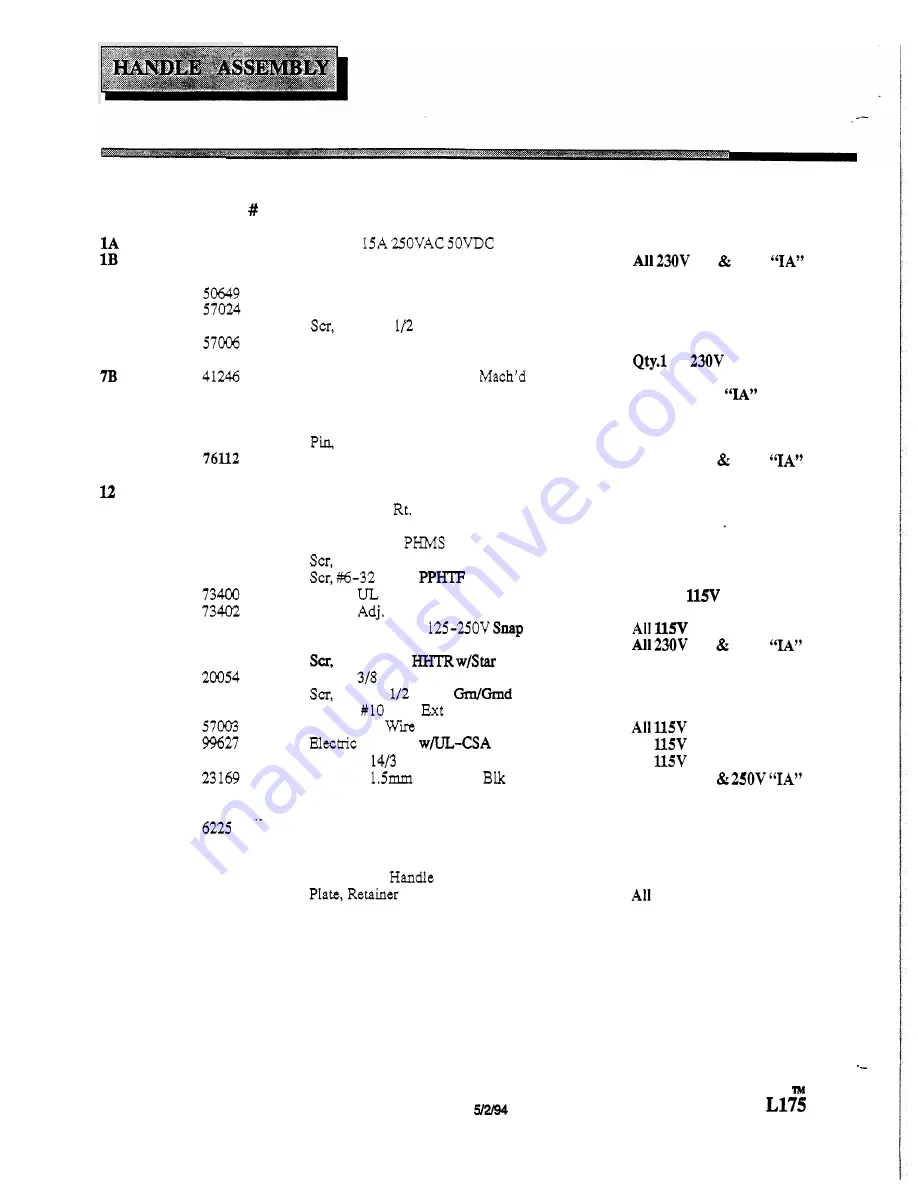
PART 

14700 
143 12 

27558 

70384 

41234 

41244 
41243 
51188 
66187 

36139 
51192 
51191 
7357 1 
70242 

7045 1 
70455 

72123 
72119 
7035 1 

70335 

87016 

23 167 

78288 
73572 

62344 
78270 
66199 
62399 
51187 

DESCRIPTION 

Breaker 
Breaker, 

7A Circuit 

Collar, C i t  

Breaker 

Label, Circuit Breaker 
Nut, 

3/8-27 Panel 

Nut, 

1/4-20 Hex Pltd 

Housing, POL Handle (Logo) 
Housing, POL Handle Rear 
Housing, POL Handle Top 
Housing, POL Handle 

Bottom 

Lever, Height Polisher Handle 

POL Handle 

Terminal 

Block, 3 position 

Grip, Handle 

Lock, 

Switch Lt. POL Handle 

Lock, 

Switch 

POL Handle 

Spring, Handle 

Lock 

Scr, 

4-40 

1/4 

Pltd. 

1/4-20 

PHTR Pltd. 

1/4-20 

1.62 SHCS Pltd 

1.00 

Pltd. 

Spacer, 

Switch 

Spacer, 

Handle 

Switch, Snap POL Handle 

230V 

Clamp, 

Nylon 

W C S A  

Washer, 

Lock 

Star 

SS 

Nut, Yellow 

Tape, 

3/4 

Cord 

Set, 

Std 

50’ 

Yellow 

Cord Set, 

Euro 

50’ 

Tube, 

Polisher Handle Merit 

Spring, Switch Handle 

Plate, Handle Lever 
Plate, Lever Plug 

Tube, 

Handle Polisher 

Pin, Polisher 

230V 

Lever, Switch Polisher handle 

Switch, 

25A SPST 

10-32 

3/8 

10-32 

PHTR 

QTY. 


Rev. 

NOTES 

“I” 

250V 

on 

”I” 

machines. 

Used 

on 

230V 

”I” machines 

only. 

Used 

on 

250V 

machines 

Used 

on 

250V “IA” 

machines 

All 230V 

“I” 

250V 

Used 

on 

machines only. 

machines. 

”I” 

250V 

machines. 

All 

machines. 

All 

machines. 

All 230V 

”I” 

230V 

”I” 

Summary of Contents for L175

Page 1: ...TE WARNING OF APOTENTIAL INJURY This product contains moving parts To reducethe risk of injury unplug the machine beforeservicing Whenever repairsare madeensureelectrical connections are correct and w...

Page 2: ...can be installedby a qualified electrician The greencoloredrigidear lug or the like extendingfromthe adaptormustbeconnectedto aper manentgroundsuchas aproperlygroundedoutlet box cover Wheneverthe ada...

Page 3: ...or lug and rotate clockwise until engaged To remove turn Counter MOTOR GEAR UNITASSEMBLY 1 2 Remove 4 bolts holdinghandle bracket aside Lift offplasticmotor shroud Tip machineback andremove 4 bolts ho...

Page 4: ...4 SWITCH fi I CIRCUIT BREAKER POWER ON INDICATOR LAMP I 115VWIRING DIAGRAM APACITOR I SWITCH CIRCUIT BREAKER 230V 250VWIRING DIAGRAM 11 SWITCH MO TOR COVER GUN w b CAPACITOR 20 m Rev 1 512 94 Ll...

Page 5: ...n 13T 44 Bearing M o t o rLower 45 cage 3Planet G e a r 46 Bearing RotatingCover 47 Cover Rotating 48 coupling 49A Spacer B h g Rev 1 5 2 94 49B 70353 3609 7035 53179 53180 73391 73393 87013 70354 310...

Page 6: ...Position Lock HandleLock Cable Spring PolisherLock Washer M10x 30 Wire Asm 115VL175 Handle Wire Am 220 25OVL175 Washer 5 16 Star Screw 1 2 13x 3 HHCS 70345 Screw 5 16 18 x 2 SHCS Rev 5 2 94 PARTNO 661...

Page 7: ...208 Use for bothsides 2 7 230V 250V Switch and Terminal Block Asm...

Page 8: ...Scr 4 40 x 1 4PHMS Pltd SC 1 4 20x 1 2PHTR Pltd Scr 1 4 20x 1 62 SHCSPltd Scr 6 32 x 1 00P P m Pltd Spacer ULSwitch Spacer Adj Handle Switch SnapPOL Handle 230V Clamp 318Nylon W C S A Washer 10 LockEx...

Page 9: ...uctionsexactly Receptacle not grounded Have an electrician inspect building s wiring Internalwiring problem Ensurethat the machineswiring matchesthe appropriate wiring diagram Replace any wires or com...

Reviews: