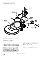
OPERATION
MB1500 98804 01/24/02
3-3
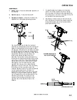
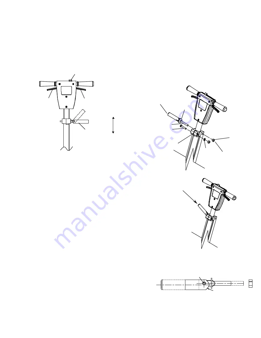
CONTROLS
1. Safety Lock –
Prevents unintended operation of
the machine.
2. Switch Levers –
Turns machine on/off.
3. Adjustment Handle –
Allows the handle to be
adjusted to a comfortable operating position.
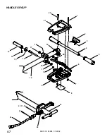
The handle adjust bar (14344) for the Merit
polishers are individually preset at the factory for
optimum locking efficiency and minimum effort
of engaging. It should not be necessary to adjust
the handle adjust bar unless the relationship of
the handle adjust bar nut (57275) or fixed clamp
bolt (70692) and their corresponding nuts
(57275) and washer (87086) have been
disturbed. The handle can be positioned to be
locked with the handle adjust bar pointing either
up or down. In order to change the position the
handle and bolt must be removed and rotated
180 degrees. It is incorrect to make it lock
opposite from the way it was assembled by
applying more force to the nut. From the factory
the locking is in the up position when the
machine handle is locked. The pivot pin (66334)
on the handle adjust bar is off center, in
relationship of the screw to the axis of the (see
drawing). To adjust handle adjust bar, tighten
nut on handle while in the locked position. The
handle is locked when the screw is to the
outside of the machine and the flat on the
opposite side of the handle is flush to the
bracket.
1. To adjust handle lock, tighten nut on handle
while in the locked position. Optimum locking
force and ease of locking is accomplished when
the locking lever nut is set to a torque of 30 to 50
inch pounds in the locked position.
2. Gap between clamp halves at the front should
be to the gap in rear when the handle adjust bar
is adjusted properly and in the locked position
(gap approximately 1/16").
2
2
1
3
LOCK
UNLOCK
SHOWN HANDLE IS
IN LOCK POSITION
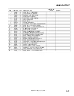
14344
67430
87202
57275 (2)
2
70692
87086
2
LOCKING SIDE FLAT
66334
PIVOT PIN CL
HANDLE C
L
1
Summary of Contents for MB1500
Page 2: ...MB1500 98804 05 19 00 1 THIS PAGE LEFT BLANK INTENTIONALLY ...
Page 13: ...MB1500 98804 01 24 02 3 5 THIS PAGE LEFT BLANK INTENTIONALLY ...
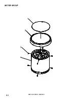
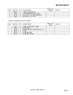
Page 16: ...MOTOR GROUP MB1500 98804 09 28 00 5 1 1 2 3 4 ...
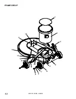
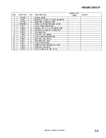
Page 18: ...FRAME GROUP MB1500 98804 09 28 00 5 3 1 2 3 4 5 6 7 8 9 10 11 12 13 14 8 15 16 ...
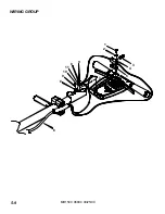
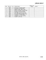
Page 24: ...WIRING GROUP MB1500 98804 09 25 00 5 9 11 6 2 1 3 4 5 10 7 9 8 9 8 ...