background image

HOW TO USE THIS MANUAL

MB1500  98804  05/19/00

         1-1

This manual contains the following sections:

-


HOW TO USE THIS MANUAL

-


SAFETY

-


OPERATIONS

-


MAINTENANCE

-


PARTS LIST

The HOW TO USE THIS MANUAL section will tell
you how to find important information for ordering
correct repair parts.

Parts may be ordered from authorized Windsor
dealers.


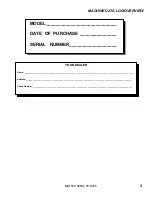
When placing an order for parts, the

machine model and machine serial number are
important. Refer to the MACHINE DATA box which
is filled out during the installation of your machine.
The MACHINE DATA box is located on the inside of
the front cover of this manual.

The SAFETY section contains important information
regarding hazard or unsafe practices of the
machine. Levels of hazards is identified that could
result in product or personal injury, or severe injury
resulting in death.

The OPERATIONS section is to familiarize the
operator with the operation and function of the
machine.

The MAINTENANCE section contains preventive
maintenance to keep the machine and its
components in good working condition.

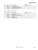
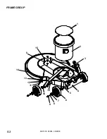
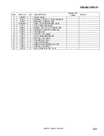
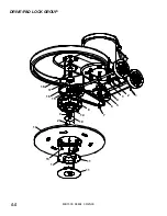
The PARTS LIST section contains assembled parts
illustrations and corresponding parts list. The parts
lists include a number of columns of information:

-


REF – 

column refers to the reference

number on the parts illustration.

-


PART NO.

 – column lists the part

number for the part.

-


QTY

 – column lists the quantity of the

part used in that area of the machine.

-


DESCRIPTION 

– column is a brief

description of the part.

-


SERIAL NO. FROM

 – column indicates

the first machine the part number is
applicable to. When the machine design
has changed, this column will indicate
serial number of applicable machine.
The main illustration shows the most
current design of the machine. The
boxed illustrations show older designs.

-

     NOTES 

– column for information not

noted by the other columns.

NOTE: If a service or option kit is installed on your
machine, be sure to keep the KIT INSTRUCTIONS
which came with the kit. It contains replacement
parts numbers needed for ordering future parts.

MODEL

  _____________________________________

DATE  OF  PURCHASE  ________________________

SERIAL   NUMBER  ____________________________

SALES REPRESENTATIVE   #  ___________________

DEALER   NAME  ______________________________

OPERATIONS GUIDE NUMBER  __________________

PUBLISHED

  ________________________________


Summary of Contents for MB1500

Page 1: ...MB1500 98804 10 19 02 G HIGH SPEED BURNISHER Operating Instructions ENG Read these instructions before using the machine MODEL MB1500 ...

Page 2: ...MB1500 98804 05 19 00 1 THIS PAGE LEFT BLANK INTENTIONALLY ...

Page 3: ..._____________________________________________________________ Address _______________________________________________________________________________________________ Phone Number _________________________________________________________________________________________ MODEL______________________________ DATE OF PURCHASE ________________ SERIAL NUMBER____________________ ...

Page 4: ... 2 1 Hazard Intensity Level 2 2 Grounding Instructions 2 3 OPERATION Technical Specifications 3 1 Handle Installation 3 2 Operation 3 3 Pad Driver Installation 3 4 MAINTENANCE Machine Troubleshooting 4 1 Wiring Diagram Notes 4 2 GROUP PARTS LIST Motor Group 5 1 Frame Group 5 3 Drive Pad Lock Group 5 5 Handle Group 5 7 Wiring Group 5 9 Suggested Spare Parts 5 11 Warranty 5 12 ...

Page 5: ...ARTS LIST section contains assembled parts illustrations and corresponding parts list The parts lists include a number of columns of information REF column refers to the reference number on the parts illustration PART NO column lists the part number for the part QTY column lists the quantity of the part used in that area of the machine DESCRIPTION column is a brief description of the part SERIAL N...

Page 6: ... near flammable fluids dust or vapors This machine is suitable for commercial use for example in hotels schools hospitals factories shops and offices for more than normal housekeeping purposes Maintenance and repairs must be done by qualified personnel During operation attention shall be paid to other persons especially children The machine shall only be operated by instructed and authorized perso...

Page 7: ...safe operation of equipment Report machine damage or faulty operation immediately Do not use the machine if it is not in proper operating condition Following is information that signals some potentially dangerous conditions to the operator or the equipment Read this information carefully Know when these conditions can exist Locate all safety devices on the machine Please take the necessary steps t...

Page 8: ...his appliance is for use on a nominal 120 volt circuit and has a grounded plug that looks like the plug in Fig A A temporary adaptor that looks like the adaptor in Fig C may be used to connect this plug to a 2 pole receptacle as shown in Fig B if a properly grounded outlet is not available The temporary adaptor should be used only until a properly grounded outlet Fig A can be installed by a qualif...

Page 9: ...e cast aluminum handle housing and belt driven pad Motor 1 75 hp Pad speed 1500 rpm Electrical system 115 volts 60 Hz Cable 50 23 m 14 3 built in cord wrap Switches Dual levers with safety lock Wheels Four 5 12 7 cm dia 1 25 3 cm wide non marking tread Handle 1 5 4 cm tubular steel adjustable easy to use thumb activated safety lock Dimensions L x W x H 31 5 80 cm X 21 5 54 cm X 43 5 111 cm ...

Page 10: ...he correct operation of the handle The spacers are positioned completely inside the pivot holes in the casting and are held in place by tightening the bolts and washers items 2 and 3 against the spacer 3 Remove bolt nut and washers items 4 5 and 6 from lower block on handle assembly Attach links as shown Tighten bolt and nut securely then back off 1 4 to 1 2 turn 4 Check handle for movement up and...

Page 11: ...e from the way it was assembled by applying more force to the nut From the factory the locking is in the up position when the machine handle is locked The pivot pin 66334 on the handle adjust bar is off center in relationship of the screw to the axis of the see drawing To adjust handle adjust bar tighten nut on handle while in the locked position The handle is locked when the screw is to the outsi...

Page 12: ...ty lock will not re engage until both levers are released 6 To stop the machine release the switch levers 7 Do not let machine rest on pad When finished with the machine return handle to the storage position NOTE The machine is equipped with a circuit breaker to protect the motor in the event an overload condition occurs The circuit breaker is located on the rear of the motor Push the reset button...

Page 13: ...MB1500 98804 01 24 02 3 5 THIS PAGE LEFT BLANK INTENTIONALLY ...

Page 14: ...ounding instructions exactly Receptacle not grounded Have an electrician inspect building s wiring Internal wiring problem Ensure that the machine wiring matches the appropriate wiring diagram Replace any wires or components which are short circuiting Repeated cuicuit breaker tripping Mechanical problem Higher amp draws indicate a mechanical problem find the problem before using the machine Faulty...

Page 15: ...Y MONTHLY Check pad wear to prevent buildup of chemicals Check pad driver system for damage Check handles switches and knobs for damage Store with pad off the floor Check all bearings for noise Check skirt bumpers for damage and replace as necessary Check overall performance of machine NOTES ...

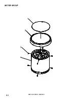
Page 16: ...MOTOR GROUP MB1500 98804 09 28 00 5 1 1 2 3 4 ...

Page 17: ... 2 27892 1 COVER ASM MOTOR 1 75HP 3 70700 8 SCR M5 X 8 X 10MM PHMS BLK 4 53249 1 MOTOR 115V 1 75 HP MOTOR COMPONENTS NOT SHOWN REF PART NO QTY DESCRIPTION SERIAL NO FROM NOTES 140411 1 CIRCUIT BREAKER 20 AMP 67029 1 RECTIFIER 14404 1 BRUSH SET MP MOTOR PKG OF 4 34378 1 FUSE 34379 1 FUSE HOLDER 09135 2 BEARING MOTOR ...

Page 18: ...FRAME GROUP MB1500 98804 09 28 00 5 3 1 2 3 4 5 6 7 8 9 10 11 12 13 14 8 15 16 ...

Page 19: ...LU 1 DECK 20 IN BURNISHER BLUE 5 03111 1 AXLE MAIN POLISHER 6 89206 4 WHEEL 5D X 1 25 X 13MM ID GRY 7 87203 8 WASHER 14MM ID X 36MM OD 8 87054 8 WASHER M8 9 70262 4 SCR M8 X 20 HHMS 10 03116 1 AXLE MAIN BURNISHER 11 70691 2 SCR M6 X 25 HHCS 12 87211 2 WASHER M6 FLAT 13 27871 2 CAP EXTRUSION 14 14423 1 BUMPER EXTRUSION 44 30 IN 15 70184 4 SCR M8 X 25HHCS 16 57276 2 NUT PUSH FLAT RD 51 ID ...

Page 20: ...DRIVE PAD LOCK GROUP MB1500 98804 09 25 00 5 5 8 14 19 20 9 15 16 17 18 7 6 5 4 3 2 1 11 11 12 13 10 ...

Page 21: ...SHER M6 20 5OD X 1 67 PLT 7 70505 1 SCR 20 X 1 00 HHCS GR5 8 64107 1 PULLEY BURNISHER 9 67449 1 RING 20M EXTERNAL SNAP 10 66337 1 PAD DRIVER 20 IN BURNISHER 11 51353 1 LOCK PAD DRIVER BLUE 12 70720 3 SCR 10 X 3 8 PPHST TYPE B 13 70201 8 SCR 20 X FHCS 14 09133 1 BEARING 20MM X 52MM 15 67450 2 RING 52MM INTERNAL SNAP 16 14424 1 BELT DRIVE 38 IN 17 09134 1 BEARING 25MM X 52MM 18 03115 1 AXLE PAD DRIV...

Page 22: ...HANDLE GROUP MB1500 98804 01 24 02 5 7 17 16 15 14 11 18 21 22 1 2 3 4 5 6 20 12 11 10 7 9 8 13 19 27 11 12 25 26 24 23 ...

Page 23: ... 3 NUT M10 X 1 5 HEX NYLOCK PLTD 12 87086 3 WASHER M10 X 30 PLTD 13 730020 1 TUBE ASSY HANDLE 14 67430 1 ROD HANDLE ADJUSTMENT 15 87202 1 WASHER BEARING HANDLE ADJ 16 66334 1 PIN PIVOT HANDLE ADJUSTMENT 17 14344 1 BAR HANDLE ADJUSTMENT 18 140393 1 BLOCK HANDLE MOUNT 19 14434 2 BUMPER BURNISHER HANDLE 20 70692 1 SCR MID X 75 HHCS PLTD 21 41366 1 HOUSING POLISHER HANDLE FRONT 22 70687 2 SCR M6 X 50 ...

Page 24: ...WIRING GROUP MB1500 98804 09 25 00 5 9 11 6 2 1 3 4 5 10 7 9 8 9 8 ...

Page 25: ...ASHER M4 SHAKEPROOF 3 73993 1 SPRING COMP 48OD X 875L 4 72123 1 SWITCH 25A SPST 125 250V SNAP 5 73989 1 SPACER SWITCH POLISHER 6 23167 1 CORD SET 14 3 STO X 50 YLW 7 57069 1 NUT ORG WIRE 2 5 18G 2 14G 8 87208 2 WASHER M5 SHAKEPROOF PLTD 9 70689 2 SCR M4 8 X 10 HHTF TYPE B 10 23207 1 CORDSET 14 3 X 48 SJT BLK 11 20005 1 CLAMP 5 16 NYLON ...

Page 26: ...RECTIFIER 14404 BRUSH SET MP MOTOR PKG OF 4 34378 FUSE 34379 FUSE HOLDER 09135 BEARING MOTOR 140397 BRACKET HANDLE LINK 89206 WHEEL 5D X 1 25 X 13MM ID GRY 87203 WASHER 14MM ID X 36MM OD 27871 CAP EXTRUSION 14423 BUMPER EXTURSION 44 30 IN 57276 NUT PUSH FLAT RD 51 RD 67449 RING 20M EXTERNAL SNAP 66337 PAD DRIVER 20IN BURNISHER 51353 LOCK PAD DRIVER BLUE 09133 BEARING 20MM X 52MM 14424 BELT DRIVE 3...

Page 27: ...1 years 6 Months Walk Behind Scrubbers 6 years 3 years 1 years 6 Months Walk Behind Sweepers 6 years 1 year 1 years 6 Months Extractors 6 years 3 years 1 years Polishers Elec Burnishers GH 6 years 3 years 1 years Wide Areas Vacuums 6 years 3 years 1 years VacPak Vacuums 6 years 1 year 1 year Air Movers Dri matic TITANä 1 year 1 year 1 year Propane Burnishers Strippers 2 year 1 year Tracer Flex Swe...

Page 28: ...r improper diagnosis 6 Tune up parts such as plugs plug wires and condensers 7 Any design alterations performed by an organization not authorized or specified by Windsor 8 Battery and charger warranties are handled directly with the manufacturer TrojanÒ batteries and LesterÒ chargers 9 High pressure washing 10 Electrical components exposed to moisture If difficulty develops during the warranty per...

Reviews: