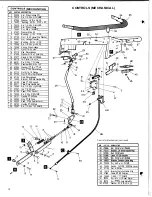
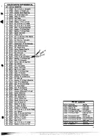
background image

(MECHANICAL) 

KEY 

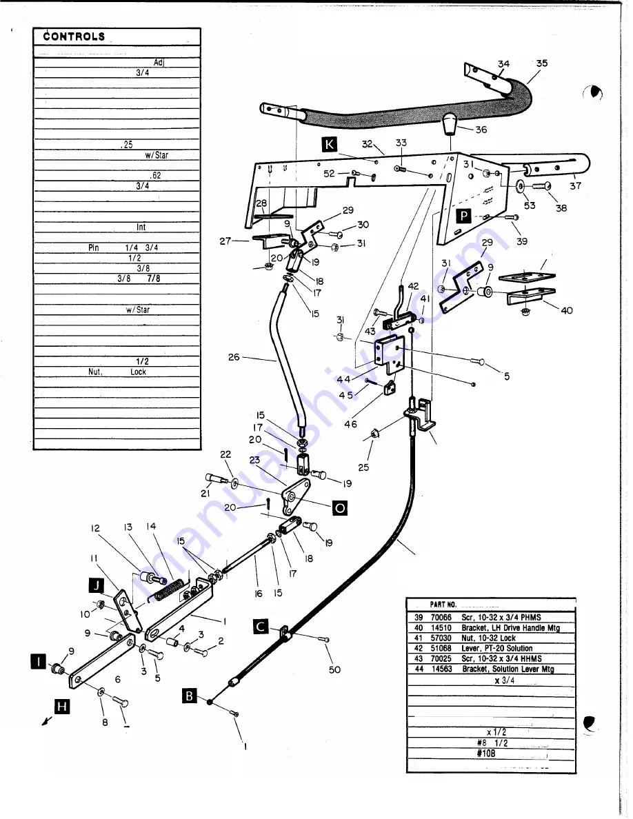
PART NO.  DESCRIPTION 

1  05029  Arm.  Drive Linkage 
2  70015  Scr.  1/4-20 x 

HHMS 

3  87090  Washer,  1/4 ID x 3/4 OD 
4  14492  Bushing, .25 ID 

.37 OD x  .25 

5  70270  Scr,  1/4-20 x 3/4 HHCS 
6  05030  Arm,  Drive Linkage 

70260  Scr.,  M6 x 16 HHMS 

8  87087  Washer,  M6 x 25 
9  14493  Bushing, 

ID 

x  .37 

OD 

10  57105  Nut,  1/4-20 Hex 

Washer 

11  05033  Arm,  Linkage Transfer 
12  14491  Bushing, .25 ID x 

OD 

14  73268  Spring,  Drive Linkage 
15  57117  Nut.  5/16-24  Hex 
16  67114  Rod,  Drive Linkage 
17  87096  Washer,  5/16 

Lock-Lite 

18  27277 

Clevis,  5/16-24  UNF Rod 

19  66116 

Clevis, 

20  66121  Pin, 3/32 x 

Cotter 

21  70273  Shoulder Bolt, 

x 1 .OO 

22  87003  Washer, 

ID 

OD 

23  90002  Yoke,  PT-20 Drive Linkage 
24  57112  Nut,  5/16-18  Flange 
25  57104  Nut.  10-32 

Washer 

26  67122  Rod,  Drive Linkage 
27  14509  Bracket, RH  Drive Handle Mtg 
28  62190  Plate,  PT-20 Support 
29  62211  Plate,  Drive Handle Arm 
30  70085  Scr,  1/4-20 x 

PHMS 

32  61 102  Panel,  PT-20 Control 
33  70054  Scr,  8-32 x 3/8  FHMS 
34  38131  Handle, PT-20 Drive 
35  36084  Grip,  PT-20 Drive 
36  48030 

Knob,  PT-20 Solution Lever 

37  38133  Handle,  PT-20 Main 

38  70057  Scr,  1/4-20 x  1 .OO  RHMS 

13  70265  Scr,  1/4-20 

SHCS 

31  57047 

1/4-20 

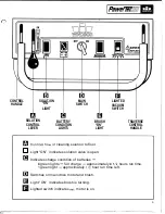
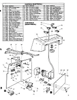
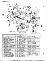
CONTROLS (MECHANICAL) 

28 

‘25 

47 

48 

49 

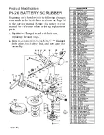
Controls (Mechanical) continued 

KEY 

DESCRIPTION 

45  70245  Scr,  4-40 

PHMS 

46  72053  Switch,  125 VDC  SPST  No  Lever 
47  57100  Nut,  4-40 Hex 
48  14519  Bracket, Solution Cable Mtg 
49  27289  Cable, 

PT-20 

Solution 

50  70085  1/4-20 

PHMS 

51  70024  Scr, 

Sheet Metal 

52 

70279 

Scr, 

Sheet Metal PH 

53 

87029  Washer,  5/16 

ID 

x 3/4 OD 

12 

Summary of Contents for PowerTec20

Page 1: ......

Page 2: ...trical components of the machine dry Lead acid batteries generate gases which can cause an explosion Keep sparks and flames away from the batteries Charge the batteries only in a well ventilated area...

Page 3: ...Controls flow of cleaning solution to floor Light ON indicates solution valve is open Indicates charge condition of batteries 4 green lights full charge approximately 4 112 hours run time 1 green ligh...

Page 4: ...TE Dis connect the AC power cord from the wall receptacle before removing the DC charger plug from machine 2 Check water level In batteries Add distilled water as needed 3 Attach brush or drive pad to...

Page 5: ...sure battery charger is dlscon nected 3 Make sure all switches are OFF 4 Remove batteries as required or dlscon nect main battery leads from batteries when making repairs to electrical system VACUUM...

Page 6: ...er bearing from hub use a piece of 314 dia tube to drive out bearing SQUEEQEEASSEMBLY To remove squeegee assembly 1 Depress pedal to raise squeegee 2 Pull retaining pin from locator stud 3 Push down o...

Page 7: ...lt when the traverse handle is in the neutral position 1 Start the brush motor and lower the brush slowly to the floor When the rear of the brush A touches the floor the To adjust clearance A Remove l...

Page 8: ...VAC BATTERY TANK 7 VAC BATTERY TANK REV PARTNO mnitvion 32 9 70280 Stud 1 4 Turn Fastener 10 70076 Scr 10 32 x 1 FHMS 11 51074 Lug Shroud Mounting 12 48012 Knob 5 16 18 8...

Page 9: ...1 7 AI 1 6 9...

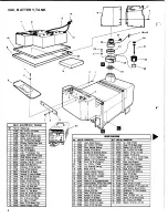
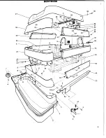
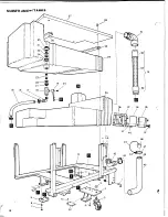
Page 10: ...MAINFRAMEWITANKS 38 I 34 37 36 35 39 41 i o 1 3 14 1 46...

Page 11: ...SQUEEGEE w ARM 59 69 21 1 I __ 11...

Page 12: ...oke PT 20 Drive Linkage 24 57112 Nut 5 16 18 Flange 25 57104 Nut 10 32w Star Washer 26 67122 Rod Drive Linkage 27 14509 Bracket RH Drive Handle Mtg 28 62190 Plate PT 20 Support 29 62211 Plate Drive Ha...

Page 13: ...48 4 9 50...

Page 14: ...14 2 1 IAL 39...

Page 15: ...PT 20 LABELS PART NO DESCRIPTION LOCATION I inside cover On handle I50378 Instruction Card I I9387 Maintenance Under hood I 15...

Page 16: ...19 Spring PT 20 Brush Lock 63A 02095 Brush PT 20 Nylon 638 02096 Brush PT 20 Polypro 63C 02097 Brush PT 20 Extra Aggressive 630 02098 Pad Driver PT 20 64 59020 0 Ring 4125 65 57133 Nut M24 x 2 Lock 66...

Page 17: ...s shown on Page 16 in the service manual Retain this notice in your manual for reference when ordering replacement parts 1 Key 44 Changed to rod with lock nuts replacing the snap rings 2 Keys 1 2 3 4...

Page 18: ...A and G voltage should be 22 26 VDC If no voltage replace solenoid Reset vac motor circuit breaker Check motor lead connections at terminal block and inline connector near vac motor Keep all connecti...

Reviews: