
,
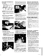
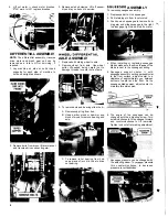
MACHINE PREPARATION
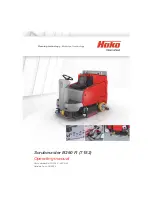
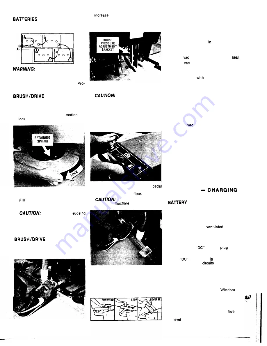
1.
Install batteries and connect battery
cables as shown.
RE
FRONT
Provide proper ventilation and
leave cover open when charging batteries.
2. Charge the batteries before using the
machine. (See Battery Charging
ced u re)
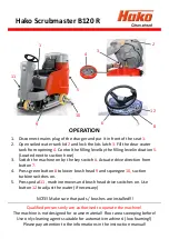
PAD ASSEMBLY
1.
Remove brush cover.
2. Position brush under drive plate and lift
brush to engage drive lugs in recesses
in plate.
A quick clockwise
will
brush to drive plate.
CLEANING SOLUTION
1.
machine with hot water and add
cleaning chemical at the proportion
noted on the container.
Always use a
low
cleaning chemical designed for use in
automatic hard surface floor scrubbers.
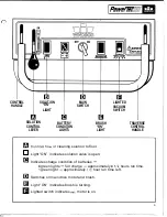
NOTE
This pedal can also be used to
brush pressure to the floor.
This can be done by pulling up on the
pedal and locking it in one of the posi-
tions on the brush adjustment bracket.
2.
Switch on brush motor by turning the
main switch clockwise.
Do
not leave brush running
on floor while machine is stationary.
3.
Switch on vacuum switch.
4.
Push solution lever forward.
NOTE:
The
amount of solution can be regulated
during operation depending on the type
of floor and the traverse speed of the
machine.
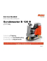
5.
Push down on front of squeegee
to release the latch arm and lower
squeegee assembly to
Always lift squeegee before
moving the
in
REVERSE
to pre-
vent damage to squeegee blades.
OPERATINO
THE
MACHINE
PAD CONTROL
1.
Push down and slightly to the left on
brush lift arm to lower brush to floor
(right hand pedal).
8.
To go FORWARD press down on the
traverse handle.
To STOP release the traverse handle and
pull back on the control handle.
To
REVERSE
machine lift up on traverse
handle.
4
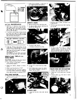
REGULAR MAINTENANCE
BEFORE STARTING
WORK PERIOD
1.
Disconnect battery charger.
NOTE
Dis-
connect the “AC” power cord from the
wall receptacle before removing the
“DC” charger plug from machine.
2.
Check water level
batteries. Add
distilled water as needed.
3.
Attach brush
or
drive pad to drive plate.
4. Check
motor and float for proper
5.
Check
hose connection at squeegee
shoe.
8.
Check squeegee blades for wear.
7.
Fill machine
hot water and add
cleaning chemical at the proportions
noted on the container.
NOTE
Use a low
sudsing cleaner designed for use in
automatic hard surface floor scrubbers.
BEFORE STORING MACHINE AT
THE END OF
WORK PERIOD:
1.
Drain both solution and recovery tanks
and rinse clean.
2.
Lift out
motor and float assembly
to allow recovery tank to air dry.
3.
Remove brush or drive pad from drive
plate and store upside down or hang on
wall.
4.
Wipe down exterior of machine with
damp cloth.
5. Raise squeegee assembly to “store”
position.
8. Charge batteries. (See Battery Charging
Procedure)
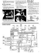
BATTERIES
AND MAINTENANCE
CHARGING PROCEDURE
WARNING:
Lead acid batteries generate
gases which can cause an explosion. Keep
sparks and flames away from batteries.
NO
SMOKING.
Always wear eye protection
when working near batteries. Charge the
batteries only in a well
area.
1.
Set the charger on a flat level surface.
2. Lift
up battery compartment cover. Leave
cover up during charging cycle.
3.
Connect the
charger
to the
connector on the machine.
N O T E
A
safety override switch is activated when
the
charge plug
connected. This
prevents all panel
on the machine
from accidentally being switched on
during charging cycle.
4.
Connect charger “AC” plug to properly
grounded outlet that has correct voltage
for the charger.
5. The charger supplied by
is
totally automatic and shuts
off when the
batteries are fully charged.
NOTE:
Refer to the charger manual for
detailed charging information.
8. After charging check electrolyte
Of
the batteries. Add distilled water to the
as shown in dlagram. (upper right)
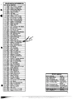
Summary of Contents for PowerTec20
Page 1: ......
Page 9: ...1 7 AI 1 6 9...
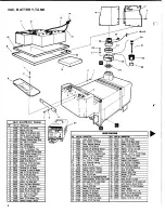
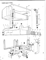
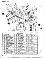
Page 10: ...MAINFRAMEWITANKS 38 I 34 37 36 35 39 41 i o 1 3 14 1 46...
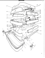
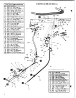
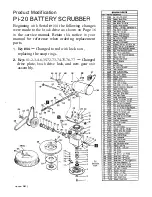
Page 11: ...SQUEEGEE w ARM 59 69 21 1 I __ 11...
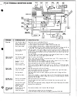
Page 13: ...48 4 9 50...
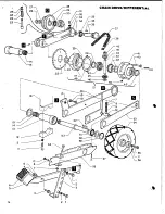
Page 14: ...14 2 1 IAL 39...