background image

TRANSPORTING MACHINE

QUICK 98560 09/20/99

3-11

TOWING OR PUSHING MACHINE

The 

QUICK© 

may be towed for short distances at

speeds not to exceed 5 mph.  Be careful to avoid
damaging machine.  Attach towing device at tie
down point.  The machine may be pushed by hand
from the rear.

NOTE: To avoid damage caused by regenerative
voltage, unplug traction motor before towing or
pushing machine.

MACHINE TIE-DOWNS

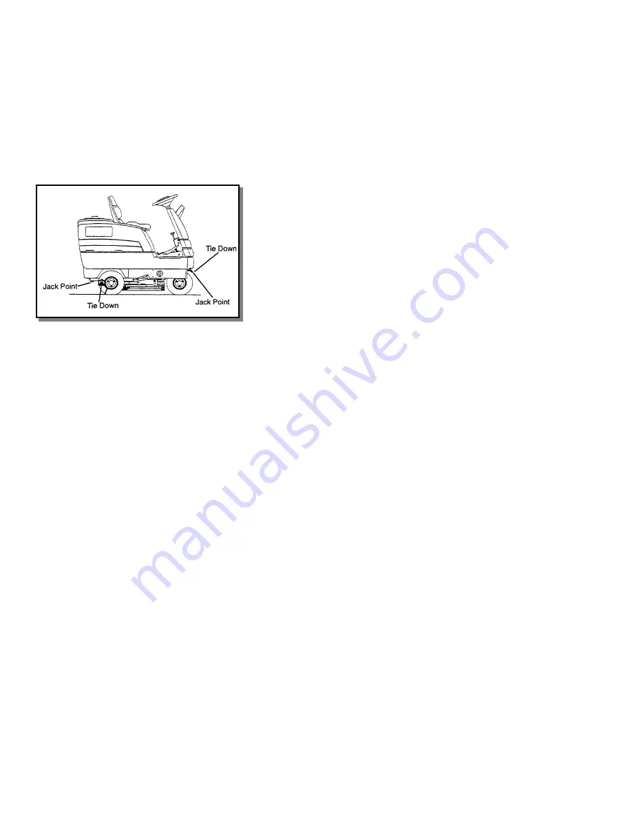
There are two tie points located at the rear, side of
the machine frame and one on the steering fork
above front tires.  Tie-down devices must be of the
proper type and strength.  The combined strength of
all tie-downs must be strong enough to lift tow times
the weight of the machine.  Tie-downs must be
positioned to prevent the machine from moving
forward, backward, or either side to side.  Use all
four corners of the machine with the tie-downs
running out opposite directions. Tie-downs must be
attached to the transporting vehicle securely.

PREPARATION FOR TRANSPORTING

Remove squeegee tool to eliminate interference with
tie-downs.
Scrub head must be in the up position before
loading.

NOTE: When transporting the machine on a trailer or
in a truck, in addition to using tie-downs, be sure to
set the parking brake, and block the tires to prevent
the machine from rolling.

MACHINE JACKING

The machine may be jacked up for service or
inspection by using the specified jack locations.
Always block the tires when jacking up the machine.

FOR SAFETY: Before leaving or servicing
machine; Stop on level surface, set parking
brake, turn off machine and remove key.

The rear jack points are the frame just behind the
rear wheels.  Remove the squeegee tool before
jacking.

NOTE: See Squeegee Tool Removal in
Maintenance Section.

The front jacking point is the steering fork just above
the front tires.

Summary of Contents for QK32

Page 1: ... ENG Mode d emploi FR Bedienungsanweisung GER MODEL QK32 QQK32 Read instructions before operating the machine Lire attentivement le mode d emploi avant la mise en service de la machine Vor Inbetriebnahme der Maschine Bedienungsanweisung lesen IPX4 ...

Page 2: ...kes 4 6 Tires and Wheels 4 6 Vacuum Motor 4 6 Batteries 4 7 To Charge Batteries 4 8 To Install Batteries 4 8 To Remove Batteries 4 9 Fuse Link 4 9 Service Schedule 4 10 Machine Troubleshooting 4 11 Propelling System Troubleshooting 4 12 User Stocking List 4 13 Electrical Schematic 4 14 PARTS LIST Battery Group 5 1 Brake Group 5 3 Circuit Breaker Group 5 5 Electrical Components Group 5 7 Floor Grou...

Page 3: ...y riders on the machine During operation attention shall be paid to other persons especially children Always follow basic safety and traffic rules Go slow on slippery surfaces and grades When leaving unattended secure against unintentional movement BEFORE LEAVING OR SERVICING MACHINE Stop on a level surface Set the parking brake Turn off the machine Remove key from switch WHEN SERVICING MACHINE Av...

Page 4: ...uthorized 1 Do Not Operate Machine And Understood Surface Agents Surfaces Brake 5 Go Slow On Grades And Slippery 3 Do Not Use Flammable Cleaning Turn Off Key And Set Parking When Parking Remove Key Unless Machine Is On A Level In Poorly Ventilated Areas Unless Main And Side Brooms 6 Before Leaving Machine Stop On Level Surface 2 Do Not Raise Hopper 4 Check For Fuel Leaks Are Turned Off SAFETY DECA...

Page 5: ... ft hour 3 5 mph with 2 in overlap Frame construction Welded cold rolled steel and steel plated Brakes Self centering mechanical 8 in 20 3 cm disc with hand lock parking brake Minimum aisle u turn width 66 in 168 cm Steering Rack and Pinon Ramp climbing 7 5 degrees Height 53 in 135 cm Length 61 in 155 cm without counterweighed bumper Length 64 in 163 cm with counterweighted bumper Width without sq...

Page 6: ...operation manual is read and understood Wear safety glasses when servicing the batteries Avoid contact with battery acid 4 Check the electrolyte level of the batteries See Batteries in the Maintenance section 5 Check the specific gravity of the batteries to determine the charge for the batteries See Batteries in the Maintenance section 6 Check for proper connection of the batteries battery to mach...

Page 7: ...cator T Solution Tank Cover U Recovery Tank Drain Hose V Lid W Solution Tank Drain Hose X Recycle Option Switch A Key Operated Switch B Directional Control Pedal C Brake Pedal D Parking Brake E Comfort Zone Operators Seat F Brush Motor Lift Switch G Squeegee Vacuum Motor Switch H Solution Control I Emergency Stop Button J Hour Meter K Battery Condition Indicator L Steering Wheel CONTROL PANEL QUIC...

Page 8: ...CONTROLS QUICK 98560 09 20 99 3 4 T N B W U C I D E L J R Q O H X V ...

Page 9: ...y tap the brake pedal FOR SAFETY Always park on a level surface turn the machine off and set the parking brake before leaving the machine of before servicing the machine E COMFORT ZONE OPERATOR SEAT F BRUSH MOTOR LIFT SWITCH One touch on the control panel brush switch automatically lowers the scrub head to the light Scrub position turns on both brush drive motors turns on the vacuum motor and lowe...

Page 10: ...ted than reconnected After a few minutes of operation the gauge will give the correct charge level NOTE See Batteries in maintenance section for more information on battery maintenance L STEERING WHEEL The steering wheel turns the front wheels of the machine causing the machine to turn M HORN BUTTON The horn button is located at the bottom of the touch panel The horn is activated by pressing the h...

Page 11: ...ontinuously until the brush switch has been pressed once again Q OPTION PUMP SWITCH Activating this switch turns on the options pump to operate a scrub wand R BRUSH CIRCUIT BREAKER MONITOR The LED will light when either of the two brush motor circuit breakers has tripped S FULL RECOVERY TANK INDICATOR This LED will light when th float senses a full recovery tank The LED will light intermittently W...

Page 12: ...lift actuators When the key is turned back on the systems will assume they are in the normal parked mode scrub deck up squeegee up and motors off Any switch command will send the selected system to the working position regardless of the position it was in when the key switch was turned off Two touches of the respective switch are required to raise the scrub deck and squeegee and turn off motors Th...

Page 13: ...d children Flammable liquids and or reactive metals can cause explosions or fire Do not pick up 1 Place left foot on brake pedal or make sure parking brake has been set 2 With directional pedal in neutral turn key switch to ON 3 Release brake 4 Press directional pedal to travel in the desired direction and steer to the start of the scrub pattern 5 Press the brush switch 1 on the console touch pad ...

Page 14: ...ist the difficult cleaning job If desired the side squeegee may be locked in the up position by raising squeegee and rotating latch EMPTYING AND CLEANING TANKS RECOVERY TANK 1 Pull the solution lever all the way up to stop solution flow if scrubbing is complete Otherwise raising the scrub deck will stop solution flow 2 Touch the scrub brush switch to raise the scrub deck stop the brush motors rais...

Page 15: ...e all four corners of the machine with the tie downs running out opposite directions Tie downs must be attached to the transporting vehicle securely PREPARATION FOR TRANSPORTING Remove squeegee tool to eliminate interference with tie downs Scrub head must be in the up position before loading NOTE When transporting the machine on a trailer or in a truck in addition to using tie downs be sure to set...

Page 16: ...ands 7 Be sure that the machine is secure 8 Service or inspect the machine as required 9 When finished working on the machine raise the machine off the jack stands 10 Remove the jack stands 11 Lower the machine to the floor Block wheels as they are lowered 12 Remove wheel block after machine has been completely lowered MACHINE STORAGE If the machine is to be stored for extended periods of time the...

Page 17: ...ine Stop on level surface set parking brake turn off machine and remove key 1 Disconnect batteries from machine 2 Locate the two bolts securing the pedal mount to the floor plate 3 Loosen the rear bolt and remove the front bolt 4 Move assembly to alternate position 5 Reinstall and tighten bolts SCRUB HEAD Refer to the Scrub Head Group in the parts manual The scrub head consists of two rotary type ...

Page 18: ...lue pads remove less finish than brown stripping pads yet will remove black marks stains and dirt Brown Pads Stripping are used for easy and complete removal of old floor waxes finishes They will quickly remove ground in dirt black heel marks and spills When used with the proper stripper this pad leaves the floor clean and ready for finishing The scrub brushes should be checked before each days wo...

Page 19: ...of the side squeegee is controlled at front by a guide that contacts the floor and at rear by an adjustment knob Check the blade and guide for damage and wear The QUICK uses a scrub deck skirt to contain the solution around the scrub brushes The scrub deck shirt is self adjusting by means of its accordion design As the brushes wear the skirt assembly will automatically remain in contact with the f...

Page 20: ...squeegee 2 Turn off the key switch and set the machine parking brake FOR SAFETY Before leaving or servicing machine Stop on level surface set parking brake turn off machine and remove key 3 Unlock and pull open latch on right rear side of tool 4 Remove blade retainer strap from squeegee tool 5 Remove squeegee blade from locating pins on squeegee tool and rotate to new position or replace as requir...

Page 21: ... all the way across tool This should correspond to the bubble being in the middle position of the spirit level 4 To decrease the deflection of the squeegee blade at the ends loosen plastic knob on squeegee railing arm To increase the deflection at the ends of the squeegee assembly tighten plastic knob on trailing arm 5 Again check the deflection of the squeegee blades Repeat steps 1 through 4 unti...

Page 22: ...every 200 hours of operation The brake should be adjusted so that the disc pads are as close to the disc as possible without causing brake to drag FOR SAFETY Before leaving or servicing machine Stop on level surface set parking brake turn off machine and remove key 1 Jack up front of machine and support on jack stands Refer to section on JACKING MACHINE 2 Once machine is secure on jack stands rele...

Page 23: ...th batteries Charge batteries in a well ventilated area Leave solution tank raised BATTERY MAINTENANCE 1 When cleaning the batteries use a solution of baking soda and water Do not allow the cleaning fluid to enter the battery cells Electrolyte will be neutralized 2 Maintain the proper electrolyte level in each battery cell If a cell should accidentally overflow clean immediately 3 Do not add water...

Page 24: ...overflow resulting in loss of battery acid balance and damage to the machine 5 Replace the battery caps and leave them in place while charging 6 Unplug the battery connector from the machine For Safety When charging connect the charger to the batteries before connecting the charger to the AC wall outlet Never connect the charger to the AC wall outlet first Hazardous sparks may result 7 Plug the ch...

Page 25: ...one at a time 6 Prepare a suitable site to place the batteries 7 Attach suitable battery lifting device and lift batteries from the machine Batteries are a potential environmental hazard Consult your battery supplier for safe disposal methods FUSE LINK Refer to the electrical Component Group The fusible link protects the main contactors from overload and is located on electrical panel TO REPLACE F...

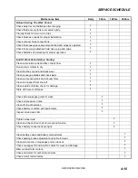
Page 26: ...m motors to dry Clean brushes or pad and check wear Clean squeegee blades and check wear Clean out recovery tank and vacuum filter Clean and inspect float shut off Clean outside of tanks check for damage Store with covers off tanks Check side squeegee guide for wear Check air pressure in tires Clean off top of batteries Check battery condition with hydrometer Inspect scrub deck skirt Tighten wheel...

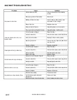
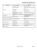
Page 27: ... LED Drain recovery tank Vacuum motor s do not run or speed varies Faulty contactor Replace contactor Circuit breaker tripped Reset breaker Loose connection Check motor wires and connections Faulty actuator Repair replace actuator Squeegee will not go down up Broken lift cable Replace cable Actuator circuit breaker tripped Reset breaker Loose connection Check motor wires and connections Scrub deck...

Page 28: ...position Full speed only Damaged wires short circuits crossed wires Check visually for damage Check controller for dirt or metal chips causing short circuit Machine will not reach full speed Batteries run down Charge batteries Little power high pitched whistle Controller overheated Allow controller to cool Check cooling fan Faulty throttle Check throttle Forward speed only Faulty controller Check ...

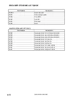
Page 29: ...OPTIONS Part Number Description 82528 Squeegee blade front red linatex standard 82529 Squeegee blade rear red linatex standard 82652 Squeegee blade side red linatex standard 82637 Squeegee blade front blue tile 82638 Squeegee blade rear blue tile 82650 Squeegee blade side blue tile 82640 Squeegee blade front green buttons 82641 Squeegee blade rear green buttons 82651 Squeegee blade side green butt...

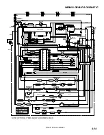
Page 30: ...E TAN 23 FUSE 200A DIODE 29215 CONTACTOR MAIN M1 SWITCH EMERGENCY RED M2 WHT 29 MOTOR CONTROLLER PM TRACTION LT BLU PM 15A FRONT VACUUM PM BLK ORG 25 RED 24 RED 12 PM MOTOR 3 HORN BLK HOUR METER 1 2 BLK GRAY BRN 22 RIGHT SCRUB BRUSH MOTOR BLU 15 PM GRAY YLW 19 REAR VACUUM MOTOR LEFT SCRUB BRUSH MOTOR PM M4 SOLUTION VALVE SOLENOID WHT TAN 11A YLW 13 22 21 20 BLK GRN GRN 7 WHT TAN BLK GRAY BRN 20 BL...

Reviews: