background image

P30LF User Manual 


Revision 1.0


Page 9 of 16 

windy

nation


01/10/2018 


Bulk Charging 

Controller will provide the battery as much of constant current as it will 
accept (up to 30 amps) as voltage increases. 

Boost Charging 

Also referred to as Absorption stage, the controller will hold the 
voltage at the Boost set point, decreasing the current until the battery 
is fully charged. 

Float Charging 

Voltage is reduced to controller set point and held constant, while the 
current is reduced to less than 1% of battery capacity. This mode can 
be used to maintain a fully charged battery indefinitely 

Equal Charging 

Controlled over charge where the voltage is brought up above typical 
peak charging voltage into the gassing stage, and held for a fixed 
period, "equalizing" the electrolyte, removing loose sulphation that 
may be on the battery plates 

No Charging 

Battery is charged or there is no charge to transfer to battery 

Temp 

Displays the measured temperature* from the BTS 

*NOTE: Temperature is displayed in Celsius and Fahrenheit


Error Condition 

The Controller will display various Error Conditions; See Section 3.6 
for details 


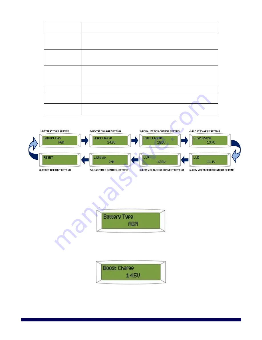
3.3  LCD


M

ENU 

I

NTERFACE 

C

YCLE


3.4  M

ENU 

I

NTERFACE 

D

EFINITIONS


The P30LF has eight different user menu interfaces to provision the controller accessible by pressing the 

MENU

 button on the front panel of the controller. Once the 

MENU

 button is pressed, you can use the 

UP

 and 

DOWN

 buttons to navigate to the desired parameter. Once visible, press 

ENTER

 to adjust the parameter. 

3.4.1 

Battery Type Setting 

In this menu, you may select the battery type you are using. 


By pressing the

 UP

 and 

DOWN

 button from this interface, you can select from the following: AGM, Flooded, 

Gel; 

Default: AGM. 

3.4.2 

Boost Charge Setting 

The value displayed i

s the Boost Charge Parameter and should be set per your battery manufacturer’s 

recommendations. 


By pressing the

 UP

 and 

DOWN

 button from this interface, you can set the value to 14.0~15.0V / 28.0~30.0V; 

Default: 14.5V/29.0V. 

3.4.3 

Equalization Charge Setting 

The value displayed is the Equalization Charge Parameter and should be set per your battery manufacturer’s 
recommendations. The 

Equalization Charge Setting is NOT available if you have selected Battery Type “Gel” 

Summary of Contents for CHC-LCD-30FM

Page 1: ...P30LF User Manual Revision 1 0 Page 1 of 16 windynation 01 10 2018 30A Flush Mount LCD PWM Solar Charge Controller CHC LCD 30FM User s Manual ...

Page 2: ...ion Charge Setting 9 3 4 4 Float Charge Setting 10 3 4 5 Low Voltage Disconnect LVD Setting 10 3 4 6 Low Voltage Reconnect LVR Setting 10 3 4 7 Load Timed Control Setting 10 3 4 8 RESET Default Setting 11 3 5 Protection Features 11 3 5 1 Electronic Short Circuit Safety 12 3 5 2 Internal Safety Fuses 12 3 5 3 Safety Per Terminal 12 3 5 4 Low Voltage Protection 12 3 5 5 Overload Protection 12 3 6 Er...

Page 3: ...ble with visual LCD graphic symbols to provide status indications of charge battery status and system faults Read this manual carefully before installing or using the controller and keep it for future reference 1 1 FEATURES Visual LCD display Intelligent 4 Stage PWM Charging Bulk Boost Float and Equalization Automatic battery charging temperature compensation User settable charging parameters offe...

Page 4: ...oper air flow 2 1 ELECTROSTATIC ESD PRECAUTIONS All electronic circuits may be damaged by static electricity To minimize the likelihood of electrostatic damage discharge yourself by touching an electrical ground e g copper pipe prior to handling the unit and avoid touching components on the circuit boards The risk of electrostatic damage is highest when relative humidity is below 40 2 2 MOUNTING T...

Page 5: ...avoid electric shock 1 Connect the Battery Connect the charge controller to the battery BEFORE connecting the solar panels to the charge controller Insert the battery wiring into the BATTERY terminals on the back of the charge controller and tighten the terminals from the top of the terminal block using a screwdriver to ensure a good connection is made Be sure to note the polarity of each terminal...

Page 6: ...ler self protection feature will prevent damage from reverse polarity connections but the load will not function until the load is connected properly A 30 amp fuse needs to be placed in the positive wire connecting the charge controller to the load See Section 3 5 for a complete fusing diagram 4 Connect the Battery Temperature Sensor BTS Optional The charge voltage required by batteries changes wi...

Page 7: ...nt For example connecting two units in parallel can allow for 60 amps of charging current and connecting three units in parallel can allow for up to 90 amps of charging current Additional parallel controllers can also be added in the future however each Controller must have its own PV array as shown below 3 OPERATION Once the controller is properly connected the main display interface will appear ...

Page 8: ...easured Values for Labeled Parameters Parameter Description SOC State of Charge Battery Capacity presented as a percentage NOTE Display will never show 100 due to character limitations BAT Battery Actual Battery Voltage IN Input current to the battery from the controller i e the current being generated by the solar panels displayed in Amp Hours NOTE Amount of current sent to battery depends on bat...

Page 9: ... and Fahrenheit Error Condition The Controller will display various Error Conditions See Section 3 6 for details 3 3 LCD MENU INTERFACE CYCLE 3 4 MENU INTERFACE DEFINITIONS The P30LF has eight different user menu interfaces to provision the controller accessible by pressing the MENU button on the front panel of the controller Once the MENU button is pressed you can use the UP and DOWN buttons to n...

Page 10: ...he set protection voltage the controller will automatically disconnect the load to prevent the battery from over discharging By pressing the UP and DOWN button from this interface you can set the value to 11 0 12 5V 22 0 25 0V Default 11 1V 22 2V IMPORTANT The smallest difference between LVD and LVR allowed is 0 8V 1 6V Be sure to first increase the LVR level for higher LVD levels 3 4 6 Low Voltag...

Page 11: ...NT There is a 10 minute delay before turning on the load in order to make sure it is really dark and not a passing cloud etc 3 4 8 RESET Default Setting By entering this mode you can reset the controller to its default settings By pressing the UP and DOWN button from this interface you can select Yes and then press ENTER to reset the controller IMPORTANT All Settings and values are reset when this...

Page 12: ...ection voltage Section 3 4 5 the controller will enter the low voltage protection state and the load will be disconnected The use of solar panels or an alternate charger is required to charge the battery to the recovery level Section 3 4 6 The controller will enter into the normal working state and power will be supplied to the load once the battery voltage exceeds the Low Voltage Protection volta...

Page 13: ...OOTING AND SUPPORT The Controller requires minimal care It is recommended to inspect all the connections at least two times per year for insulation damage or corrosion and to ensure all connections are tight and secure 5 1 MAINTENANCE CARE Clean the area around the controller of any dirt or debris with a cloth Tighten the screws on the terminals Inspect for loose broken or burnt wire connections I...

Page 14: ... or other person is authorized to give any warranties on behalf of Windy Nation not expressly set forth in this limited warranty 5 4 1 Restrictions No warranty will apply if the Product i has been altered or modified except by Windy Nation ii has not been installed operated repaired or maintained in accordance with instructions supplied by Windy Nation iii has been subjected to abnormal physical t...

Page 15: ... MODIFICATION OF THE PRODUCTS Some jurisdictions do not allow the limitation or exclusion of implied warranties or how long an implied warranty may last so the above limitations may not apply to you In any such jurisdiction the warranty shall be limited to the minimum warranty and period required by law WINDY NATION EXPRESSLY DISCLAIMS ALL LIABILITY FOR BODILY INJURIES OR DEATH THAT MAY OCCUR DIRE...

Page 16: ...P30LF User Manual Revision 1 0 Page 16 of 16 windynation 01 10 2018 6 MOUNTING TEMPLATE ...

Reviews: