background image

SunTura Solar Tracker Kit Manual 


Revision 1.0 


Page 7 of 10 

Windy

Nation 

08/09/2012 


3.2.3 

East/West Linear Actuator Installation 

The east/west linear actuator has a stroke length of 12 inches and also has two 5/16 inch diameter mounting 
holes. It is wired to the SunTura Tracking Electronics in the following manner:  If the sun is located to the 
west of the solar tracker, the east/west linear actuator will extend so it positions the solar panels 
perpendicular to the sun’s light rays. If you wish for the east/west linear actuator to retract when the sun is to 
the west of the solar tracker, then you can simply switch the grey and brown wires that are connected to 
north/south linear actuator. 
 

Note:

 Before powering up the SunTura Solar Tracker electronics be certain there is enough slack in the 

wires between both Linear Actuators and the Electronics Box to cover the full range of motion of the solar 
tracker. 

3.2.4 

Photo Sensor Installation 

For northern hemisphere installations, it is recommended that the Photo Sensor is mounted on the northern 
side of the solar tracker and that the Photo Sensor has an unobstructed view of the sky (Photo Sensors that 
are being installed in the southern hemisphere should be mounted on the southern side of the solar tracker.) 
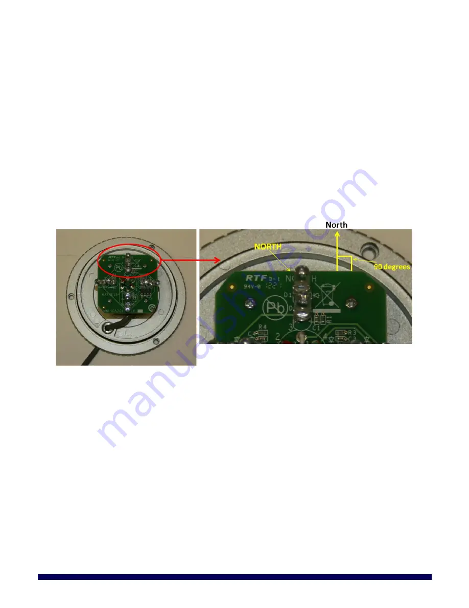
The side of the Photo Sensor 

circuit board that is labeled “NORTH” needs to be pointed towards the north. 

Note:

 The edge of the Photo Sensor 

circuit board that is labeled “NORTH” will be perpendicular (90 degrees) 

to the north; See Figure 4 below. 


Figure 4: Photo Sensor mounting orientation 


3.2.4.1 

Mounting the Photo Sensor 

Use the included Allen wrench to loosen the two set screws that secure the dome to the Photo Sensor. After 
the set screws are removed, pull off the Photo Sensor Dome. Note that it is easier to remove the Photo 
Sensor Dome if a flat head screw driver is used to help lift up the Photo sensor Dome. See Figure 5 below. 

Summary of Contents for SunTura SOT-TRKS-NF

Page 1: ...SunTura Solar Tracker Kit Manual Revision 1 0 Page 1 of 10 WindyNation 08 09 2012 WindyNation SUNTURA SOLAR TRACKER SOT TRKS NF User s Manual ...

Page 2: ...ty 4 2 Product Overview 5 2 1 Features 5 2 2 Safety Precautions 5 3 Installation 5 3 1 Parts List 5 3 2 General Installation Guidelines 5 3 2 1 Electronics Box Installation 5 3 2 2 North South Linear Actuator Installation 6 3 2 3 East West Linear Actuator Installation 7 3 2 4 Photo Sensor Installation 7 3 3 Fine Tuning the LED s for Optimal Solar Tracking 8 4 Troubleshooting And Support 10 4 1 Car...

Page 3: ...been installed operated repaired or maintained in accordance with instructions supplied by Windy Nation iii has been subjected to abnormal physical thermal or electrical stress misuse negligence or accident If Windy Nation determines that the problem with the Product is not due to a manufacturing defect in Windy Nation s workmanship or materials or otherwise does not qualify for warranty repair th...

Page 4: ...TION OF THE PRODUCTS Some jurisdictions do not allow the limitation or exclusion of implied warranties or how long an implied warranty may last so the above limitations may not apply to you In any such jurisdiction the warranty shall be limited to the minimum warranty and period required by law WINDY NATION EXPRESSLY DISCLAIMS ALL LIABILITY FOR BODILY INJURIES OR DEATH THAT MAY OCCUR DIRECTLY OR I...

Page 5: ...eath Always disconnect the SunTura Solar Tracker electronics from its power supply before approaching the solar tracker 3 INSTALLATION 3 1 PARTS LIST 1 Electronic Controller Box 2 Photo Sensor Dome 3 East West Linear Actuator 4 North South Linear Actuator Figure 1 SunTura Solar Tracker Kit Parts List 3 2 GENERAL INSTALLATION GUIDELINES The SunTura Solar Tracker Kit provides the electronics used to...

Page 6: ... be permanently destroyed Even if the voltages exceeds 30 VDC for only just an instant the electronics will be permanently destroyed Windy Nation Inc recommends a car sized 12 volt battery to power the SunTura Solar Tracker electronics The red wire coming out of the Electronics Box connects to the positive output of the DC power supply The black wire coming out of the Electronics Box connects to t...

Page 7: ...onics Box to cover the full range of motion of the solar tracker 3 2 4 Photo Sensor Installation For northern hemisphere installations it is recommended that the Photo Sensor is mounted on the northern side of the solar tracker and that the Photo Sensor has an unobstructed view of the sky Photo Sensors that are being installed in the southern hemisphere should be mounted on the southern side of th...

Page 8: ... step is optional The SunTura Solar Tracker should track the sun with an accuracy of 7 degrees or better with no fine tuning Mounting the Photo Sensor slightly off angle human error with respect to the solar tracker can lead to a slight tracking inaccuracy If you wish the LED s can be adjusted to provide optimal tracking accuracy Do NOT attempt to fine tune the LED s until the Photo Sensor has bee...

Page 9: ...LED s on the Photo Sensor circuit board To adjust the LED s use the following table LED Adjustment Direction Result D1 and D2 move up move down track more north track more south D3 and D4 move up move down track more south track more north D5 and D6 move up move down track more east track more west D7 and D8 move up move down track more west track more east It is highly recommended that the LED s ...

Page 10: ... Section 3 3 Tracker is not working 1 Check the fuse as shown in Section 3 2 1 2 Test the source voltage to the tracker Electronics Box 3 Check connections to the red and black wires going to the Electronics Box 4 3 SUPPORT If you are experiencing technical problems and cannot find a solution in this manual you can contact Windy Nation Inc for further assistance Call 805 323 6445 Email info windyn...

Reviews: