1
SPECIFICATIONS
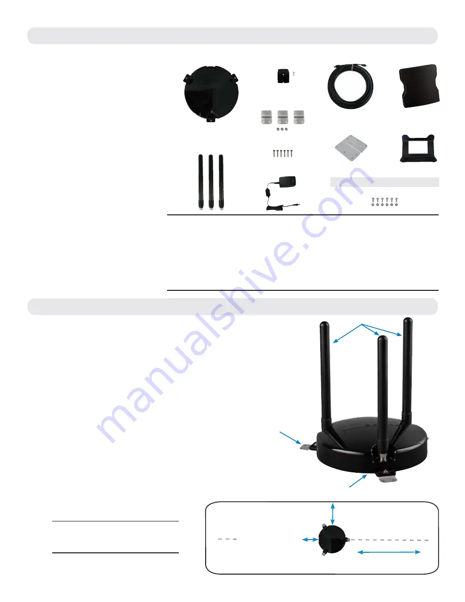
PARTS LIST
EXTERIOR INSTALLATION
WARNINGS:
• Do not paint any portion of the Winegard
®
ConnecT
™
WF1. Painting the system
could damage the system and will void the warranty.
• Do not mount closer than 12 inches from the edge of the roof.
• Do not mount closer than 24 inches from adjacent devices.
• Do not mount the outdoor unit (ODU) with the cable facing the front of the vehicle.
1)
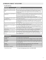
Remove each antenna from the protective bag
and screw it into an open port on the outdoor unit
(ODU).
See Figure 1
.
2)
Firmly tighten each antenna by hand. If using a
wrench, do not overtighten the antenna as the
antennas or housing may become damaged. The
antennas should be tightened to 20–25 inch pounds
of torque.
3)
Attach the mounting feet to the unit by threading
the provided nuts to the post on the mounting feet.
Tighten nuts using an 11/32” wrench.
See Figure 1
.
4)
Place the unit on the roof in the chosen location.
Connect the cable to the ODU. Ensure that the
Ethernet cable exits the unit towards the back of
the vehicle.
See Figure 2.
TIP:
Clean the roof where the unit will
be mounted to ensure a good seal.
Wireless Standard
802.11a/b/g/n/ac
Frequency Band
2.4GHz, 5GHz Simultaneous (5GHz indoor unit only)
Wireless Speed (max)
2.4GHz: 450Mbps (Rx), 450Mbps (Tx)
5GHz: 1300Mbps (Rx), 1300Mbps (Tx)
Amplifiers
Outdoor:
(3) 2.4GHz amplifiers
Indoor:
(3) 2.4GHz amplifiers
(3) 5GHz amplifiers
Wireless Security
WEP, WPA, WPA2, WPA mixed
Antennas
Outdoor:
(3) Detachable high gain 5dBi antennas
Indoor:
(3) Internal 2.4GHz 4dBi antennas
(3) Internal 5GHz 6dBi antennas
Ports
(1) RJ45 10/100/1000m Lan Port (IDU only)
(1) RJ45 PoE (ODU
&
IDU)
(2) USB 2.0 Ports
Power Rating
Switching, AC Input 100-240v, 1.5A
Setup Requirements
Wireless 802.11a/b/g/n 2.4GHz network
Computer, tablet or smartphone with a
web browser
Outdoor 2.4ghz
Antennas (3)
Outdoor Unit (ODU)
Indoor Unit (IDU)
Power Adapter
25’ Ethernet Cable
Indoor Unit Stand
Mounting Feet
w/Nuts (3)
Mounting Screws (6)
Outdoor Unit Cable
Entry Cover w/Screw
Cable Entry Plate
Figure 1
Figure 2
FOR OPTIONAL ACCESSORY MOUNTS:
Accessory Screws
& Nuts
(6 each)
or adjacent devices
≥24
″
to front of vehicle
Cable connection
facing back of vehicle
Fr
o
n
t o
f v
eh
ic
le
≥12
″
to edge of vehicle
B
ac
k o
f v
eh
ic
le
Foot attached to ODU
Antenna secured to ODU
Antennas


