background image

9

Signal strength screen meter shows some
signal strength, but constantly moves up and
down, and is never locked on satellite.

Unit continues to move, but never finds any signal.

The unit continues to move and the signal strength
screen shows that it is finding the satellites, but will
never lock onto any satellite. Continues to search.

The unit moves around in circles, then points off
the front of the coach.

The unit moves in circles and does not find the sat-
ellite, then begins to make grinding noise.

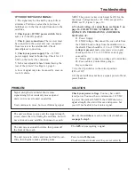
NOTE: The power rocker switch must be ON for the
next steps. Voltage must be +12 VDC, except at the
LNBF, see #2, Figure 9, page 10.

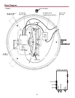
6. To check voltage at  connections, see Figure 9 on
page 10. FOLLOW THE NUMERICAL SE-
QUENCE ON THE DRAWING AND CHECK
VOLTAGE AT:

#1. Power Supply.
#2. LNBF voltage. Disconnect the coax cable from
the LNBF. Check voltage from the middle wire to
the shield. There should be +12 to +19 VDC. If no
voltage is present
, make sure receiver is on and
check again for +12 to +19 VDC at ends of gray
coax cable.
#3. ‘Mini-cable’ connection voltage at Control Box.
#4. Coax cable at Control Box going to
Heyco connector.

7. Are the dip switches in the correct position
(101 or 119)?

8. If the unit still does not have a signal, power off and
power back on.

IF YOU DO NOT HAVE A SIGNAL:

1. The signal may be blocked by trees, hills or
structures. Pull into an area where no trees or
buildings are in the line of sight from unit to the
satellites.

2. Check your +12 VDC power switch. Make
sure it is in the ON position.

3. Check  your connections. The receiver must
be connected to the power and coax connected
from receiver to the satellite dish. Check
demultiplexer connection.

4. Check your power supply. The +12 VDC
power supply must be hooked up. Check for +12
VDC on the roof at the connector.

5. Is the rear adjustable base bracket facing the
rear of the vehicle? See Figure 1, page 4.

6. Loss of signal may also be caused by snow on
roof of vehicle.

Check your power voltage. You may have unfil-
tered power. You must have a minimum of 12 VDC
to power the stacked LNBF. If the LNBF shows no
signal strength, the unit will move and operate, but
you will not be able to lock onto a signal.

PROBLEM

SOLUTION

Be sure the switches are set on the correct numbers —
see page 5, step 5.

The GPS is not acquiring a signal.

Power unit off, then on.

Check switches to make sure they are set correctly.

Troubleshooting

Summary of Contents for Movin' View MV-0055

Page 1: ...or Single Receiver Model MV 0055 Made in the U S A U S Patent Nos 6 023 247 6 188 300 Winegard Company 3000 Kirkwood St Burlington IA 52601 2000 319 754 0600 FAX 319 754 0787 www winegard com Printed in U S A Winegard Company 2002 2451022 1 02 WINEGARD ...

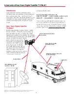
Page 2: ...plink signal amplify it and then transmit it back to earth in the Ku frequency band This signal is concentrated and reflected to the LNBF located at the focal point of the dish The LNBF amplifies and converts the signal to the 950 to 2050 MHz range The signal is then passed through a coaxial cable to the receiver where individual channel selection and processing take place For Programming informat...

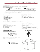
Page 3: ... caution should be taken Indicates suggestions to make processes easier for you PARTS INCLUDED 1 Radome 3 base mounting feet 1 Power switch 2 Wall plates white brown 1 Surface mount bracket 2 Cable clamps 1 Cable entry plate LIFT UNIT STRAIGHT UP TOOLS NEEDED FOR UNPACKING INSTALLATION UNPACKING THE UNIT 7 16 open end wrench Level Drill w 3 4 bit 1 1 4 hole saw if mounting switch in wall 5 16 Sock...

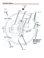
Page 4: ...SE FOOT MUST DIRECTLY FACE REAR OF VEHICLE SWITCH LOCATION POWER SUPPLY AZ MOTOR COUNTERWEIGHT Remove wire ties holding mount EL MOTOR LEVELING SCREW ADJUSTABLE BASE FOOT LEVELING SCREW LEVELING SCREW HEYCO CONNECTORS GPS ANTENNA REAR ADJUSTABLE BASE FOOT FRONT OF VEHICLE ...

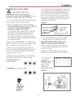
Page 5: ...ce 2 Select a level spot on your roof for installation The unit should be no more than 1 off level Be sure no roof mounted equipment is blocking the satellite line of sight You will need to decide where the wires will enter the vehicle A coax and an 18 gauge power wire will need to be placed in the vehicle The power wire will go to the nearest 12 VDC power source the coax will be routed to your sa...

Page 6: ...d side edge of vehicle 90 from rear mounting bracket Figure 6 The recommended location for the GPS antenna is based on having a level location and a clear view of the sky If another location further from the base is desired loosen the Heyco connector and pull out addi tional wire in the base You must re wrap and re tie the GPS cable inside the dome to prevent interfer ence with the LNBF Failure to...

Page 7: ... spade on switch c Connect red wire from unit to small red spade connector d Connect red spade connector to center spade on switch e Connect 12 VDC wire from vehicle to small red spade connector f Connect red spade connector to isolated spade on switch Cable entry installation 1 Connnect the coax cable from the roof to the Sat ellite In connection on the receiver Connecting the receiver Installati...

Page 8: ...scribing to multi satellite programming The MV 0055 will toggle between two different satellites Both DIRECTV and DISH Network have programming on more than one satellite When a channel is selected on the remote con trol and it is not located on the satellite the unit is currently on the system on the vehicle will automatically move to the new satellite DIRECTV programming 1 There is NO SETUP requ...

Page 9: ...l Box going to Heyco connector 7 Are the dip switches in the correct position 101 or 119 8 If the unit still does not have a signal power off and power back on IF YOU DO NOT HAVE A SIGNAL 1 The signal may be blocked by trees hills or structures Pull into an area where no trees or buildings are in the line of sight from unit to the satellites 2 Check your 12 VDC power switch Make sure it is in the ...

Page 10: ...PPLY 1 POWER SUPPLY POWER WIRE SEE DETAIL 4 COAX CABLE AT CONTROL BOX 3 CONTROL BOX TO LNBF EL MOTOR 2 LNBF VOLTAGE HEYCO CON NECTORS AZ MOTOR GPS ANTENNA FIGURE 9 TO RECEIVER TO LNBF CONTROL BOX DETAIL DO NOT USE AZ MOTOR EL MOTOR 8 PIN POWER T A GPS ...

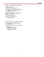
Page 11: ... user input required No data port required for DISH NetworkTM DIRECTV or ExpressVu Tracking greater than 30 Elevation range 14 5 to 74 5 azimuth unlimited 30 power cable and 30 coaxial cable included Manufactured from sturdy ABS plastic UV protected Off white color compatible with all vehicles Compact size 32 diameter 15 height Weight of unit 43 lbs Shipping weight 59 lbs ...

Page 12: ...ove address Winegard dealers will arrange for the replacement or repair and return to you without charge the product which failed due to defective material or workmanship WINEGARD COMPANY WILL NOT ASSUME ANY LIABILITIES FOR ANY OTHER WARRANTIES EXPRESS OR IMPLIED MADE BY ANY OTHER PERSON ALL OTHER WARRANTIES WHETHER EXPRESS IMPLIED OR STATUTORY INCLUDING WARRANTIES OF FITNESS FOR A PARTICULAR PURP...

Reviews: