background image

5

Assembly & Installation

Things you need —

Screwdrivers (Phillips and slot)
1-3/4” hole saw
7/16” wrench

ABS glue
Drill with 1/8” bit
Tape measure

Non-hardening sealant

(Check manufacturer’s specifications for
compatibility with your roof material.)

STEP 1.

 Choose a location on the roof for dish that will allow dish to raise and rotate without

interfering with other roof-mounted equipment. Make sure inside ceiling plate is easily acces-
sible, and with no obstructions that would interfere with operation.

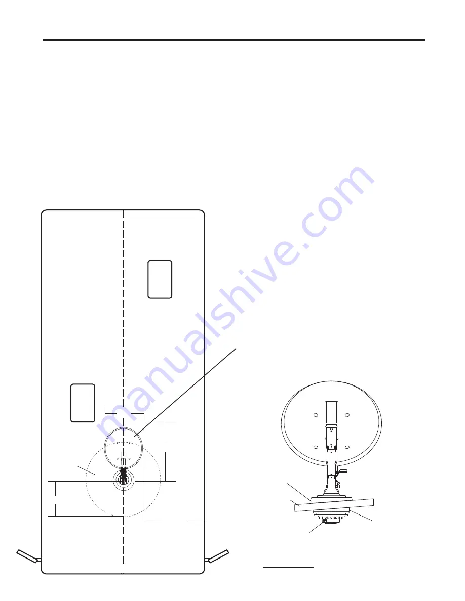
Figure1 shows minimum distance (10”) antenna should be located from edge
of vehicle roof. It is recommended that you check with your dealer or manufacturer
for provisions that may have been made in the roof for antenna mounting; a
reinforced roof area or pre-wire installation from the factory.

NOTE: 

The system must be level for proper operation!

Winegard Model RW-5000 roof wedge with gasket is available. If inside roof wedge is
needed, Winegard’s RW-1000 can be trimmed to fit ceiling plate.

MEASURE THE THICKNESS OF THE ROOF

NOW

. Measure the outside roof covering

through ceiling material. You will need this
information when installing ceiling plate/
directional handle assembly.

STEP 2. 

Position template on roof (see insert page

of this manual). 

CAUTION: DO NOT drill through

wiring.

Carefully

 drill a 1-3/4” hole through roof and

ceiling of vehicle. 

Inspect hole to make sure

wiring is intact. (Roof template, see insert.)

It is highly recommended that the antenna be
mounted on roof center line. Do not mount
antenna closer than 10” from edge of roof.

NOT TO SCALE

RW-5000

Roof Wedge

with gasket

Vehicle Roof

Antenna Controls

Interior

 Roof Wedge

(Optional)

FIGURE 3

Rev. 7/04

Center Roof Line

MINIMUM

10”

17” RADIUS

26”

19.50”

34” DIAMETER

OPERATING

AREA

FRONT OF VEHCILE

z

Summary of Contents for RM-4600

Page 1: ...V DIGITAL SATELLITE SYSTEM Model RM 4600 may also be packaged as RM 4604 RM 4646 Made in U S A Winegard Company 3000 Kirkwood St Burlington IA 52601 2000 319 754 0600 FAX 319 754 0787 www winegard com Printed in U S A Winegard Company 2002 2006 2451067 Rev4 9 10 ...

Page 2: ... and move the dial until the pointer on the directional handle points toward the number given for azimuth indicated on the menu on your receiver Example If the receiver indicates point antenna at 145 rotate directional handle so pointer is pointing at 145 on the directional dial Step 5 If you do not have a signal at the Azimuth indicated by your receiver you may have to rotate the dish UP TO 20 de...

Page 3: ... meeting resistance The number of turns will vary according to the elevation angle the antenna was set at STEP 4 Move rotation clamp to the LOCK position Antenna is now locked in travel position STEP 5 Snap elevation crank in place CAUTION NEVER LOWER ANTENNA IN ANY POSITION EXCEPT TRAVEL POSITION DO S 1 Do check parking location for obstructions before raising antenna 2 Do carefully raise lower a...

Page 4: ...OTATE OR IS HARD TO ROTATE 1 Inspect antenna on roof Make sure that mount has not been damaged 2 Check for caulking between gear housing and baseplate 3 Be sure cables are not binding and that they are installed properly 4 Contact Dealer or Winegard Service Department ANTENNA DOES NOT RAISE OR IS HARD TO RAISE 1 Inspect antenna on roof Make sure that mount has not been damaged 2 Check for caulking...

Page 5: ...om the factory NOTE The system must be level for proper operation Winegard Model RW 5000 roof wedge with gasket is available If inside roof wedge is needed Winegard s RW 1000 can be trimmed to fit ceiling plate MEASURE THE THICKNESS OF THE ROOF NOW Measure the outside roof covering through ceiling material You will need this information when installing ceiling plate directional handle assembly STE...

Page 6: ... of the vent tube extending from the hole Put a small amount of sealant on the roof under the vent tube end to hold in place FIGURE 5 4 Antenna Mounting Bolts 4 1 4 20 HEX NUTS FIGURE 6A Install cable entry plate 3 minimum from mount base CAUTION DO NOT GET sealing compound between Base Plate and Rotating Gear Housing DO NOT PAINT top of Base Plate or around Rotating Gear Housing STEP 5 Facing the...

Page 7: ...extension if the directional handle must be extended by less than 2 1 4 cut the directional handle to fit NOTE Be sure large and small keyways line up in the hub and directional handle Roof Directional Threaded Worm Gear Thickness Handle Length Rod Length Shaft Length Figure 9 Figure 11 1 1 2 2 7 8 2 3 4 2 7 8 1 3 4 3 1 4 3 3 1 8 2 3 1 2 3 1 4 3 1 2 2 1 4 3 7 8 3 1 2 3 7 8 2 1 2 4 1 8 3 3 4 4 1 8 ...

Page 8: ...hreaded rod Tighten the nut enough to snug the directional handle to the hub STEP 14 Install the nut and washer on the threaded rod Tighten the nutenough to snug the directional handle to the hub CUTTING SHAFT LENGTH Figure 11 Flip down handle on the elevating crank handle Slide elevating crank handle up shaft until snug against directional handle Mark the elevating shaft at inside bottom surface ...

Page 9: ...NITIAL INSTALLATION the antenna SHOULD ROTATE APPROXIMATELY 360 DEGREES FROM TRAVEL POSITION The pointer on the DIRECTIONAL HANDLE should point towards the RED SCREW on the ROTATION CLAMP when in TRAVEL POSITION FIGURE 14 Rev 6 10 Red Screw POINTER MUST POINT TO RED SCREW ON ROTATION CLAMP WHEN IN TRAVEL POSITION Rotation Clamp ...

Page 10: ...utaway view of mount gear housing Cast Aluminum Gear Housing Worm Gear Elevating Gear Part of RP 30RM kit Vent Tube Outer Bearing Seal Part of RP 30RM kit Spring Turret Pivot Shaft Part of RP 30RM kit Pivot Bearing Part of RP 30RM kit Rotate Limit Plate Screw Inner Bearing Elevate Shaft Gear Hub Turret Base Screw O Ring RP 4400 Spacer ...

Page 11: ...Parts List 11 Rev 4 16 ...

Page 12: ...Parts List 12 ...

Page 13: ...Notes 13 ...

Page 14: ...Notes 14 ...

Page 15: ...Notes 15 ...

Page 16: ... is at the sole discretion of Winegard Company Alternatively Customer may ship the product prepaid to Winegard Technical Services located at 3111 Kirkwood Street Burlington Iowa 52601 Telephone 800 788 4417 Customer must return the product along with a brief description of the problem and provide Winegard Technical Services with Customer s name address and phone number Customer must also provide p...

Reviews: