background image

2

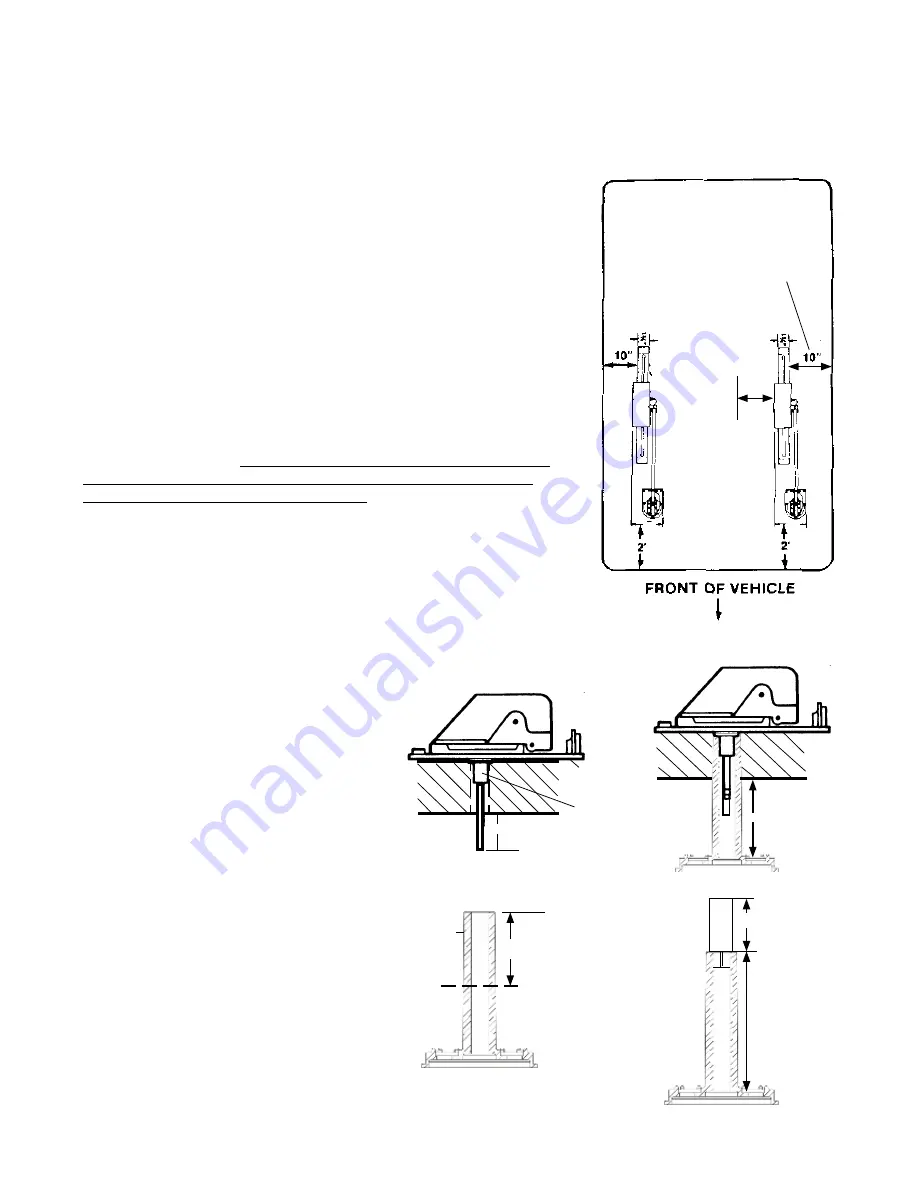
NOTE: Figure 1 shows the minimum distance the mount can be 

located from edge of vehicle roof or nearest obstruction. Check with 

your dealer or the manufacturer for information about options in the 

roof for mounting the antenna. A reinforced roof area, or a prewired 

coax cable, may be available. For sloped/round roofs, use Winegard 

Model RW-2000 exterior roof wedge, to level installation. An interior 

wedge, IW-5000, is also available.
STEP 2:

 Using template on our website at http://www.winegard.com/

kbase/upload/sensar_template.pdf  drill 1-3/4" hole through roof and 

ceiling of vehicle. Be careful not to damage any wiring between roof and 

ceiling.

STEP 3: 

Drill 1/2" hole for 

cable entry through roof of vehicle only

. DO 

NOT DRILL THROUGH CEILING. Route cable through ceiling and wall to 

power supply location.

STEP 4: 

The mount is designed to fit roofs from 1" to 4-3/4" thick. As 

supplied, the mount will fit a roof 4-3/4" thick. If roof is less than 4-3/4" 

thick, cut elevating shaft and directional handle to size, steps shown 

in figures 2, 3, 4 and 5. 

If roof is more than 4-3/4" thick (max. 7"), a 

directional handle extension is needed. Order Winegard Model 


EK-1036, Directional Handle Extension. 

IMPORTANT

The handle and extension must be glued together 

after 

checking that you have the correct length

The handle will not work 

properly if it is not glued together! (PVC glue is recommended; for your 

safety, use according to manufacturer's directions.)

NOTE: If using roof wedge RW-2000 or interior wedge IW-5000, put in 

place before installing base plate or interior hardware.

2452013-Installation/Operation

STEP 1: 

Choose location for antenna. Figure 1 illustrates placement of the Sensar, showing it in travel position. 

You must be able to raise and rotate antenna without interfering with other roof-mounted equipment. Make sure 

inside ceiling area is clear to mount ceiling plate.

3¾"

10" Minimum

Distance

3¾"

10"

To Nearest 

Obstruction

STEP 5:  

Center elevating shaft in hole on 

roof. Temporarily secure base plate to roof 

with two screws provided.

 (Do not apply 

sealant at this time).

 Inside unit, make a                                                                                 

mark on the  shaft 1-1/2” below ceiling and cut  

shaft on this mark. See figure 2.  

After cutting elevating shaft, push directional 

handle up into ceiling over shaft being careful 

to align keys inside directional handle onto 

keyways on bottom of gear housing. 

(NOTE: 

The keys only line up one way; do not force. 

TIP: Pointer on directional handle should 

point toward back of coach if properly 

installed.)

 Make sure directional handle is snug 

against bottom of baseplate. Measure distance 

between the bottom of the recess on the handle 

to the ceiling. See figure 3. Pull handle back 

down and transfer this dimension to the shaft 

end of the directional handle. Mark it and cut it 

off here, fig. 4.  

If EK-1036 (directional handle extension)


is 

used, 

DO NOT CUT EK-1036 extension.

 Cut 

excess length from directional handle only. The 

handle and extension must be glued together 

after checking that you have the correct length, 

fig. 5

10"

10"

FIGURE 1

FIG. 4

Measure from

the recess on 

top of handle 

to the ceiling.

FIG. 2

1-1/2"

FIGURE 3

FIGURE 5

EK-1036

Extension

DO NOT CUT

extension

Cut excess 

length from 

directional 

hande

Measure 

from bottom 

of recess on 

top of handle

Bottom of 

Baseplate

Bottom 

of Gear 

Housing

Directional Handle

Shaft 

End

*

Transfer the 

measurement 

from Fig. 3 to 

shaft end and

cut off.

*

2-1/4"

Summary of Contents for SENSAR III

Page 1: ...red RV WING White RV GS WING Gray Residential Sensar only Sensar with Wingman VHF UHF VHF UHF Excellent Digital Reception Great Digital Reception Digital Reception Sensar vs Sensar with Wingman Channels 14 51 Channels 2 13 Channels 14 51 Channels 2 13 SENSAR III ANTENNA SENSAR III ANTENNA WITH WINGMAN ACCESSORY Printed in U S A Winegard Company 3000 Kirkwood Street Burlington Iowa 52601 2000 Wineg...

Page 2: ...eration STEP 1 Choose location for antenna Figure 1 illustrates placement of the Sensar showing it in travel position You must be able to raise and rotate antenna without interfering with other roof mounted equipment Make sure inside ceiling area is clear to mount ceiling plate 3 10 Minimum Distance 3 10 To Nearest Obstruction STEP 5 Center elevating shaft in hole on roof Temporarily secure base p...

Page 3: ...les in ceiling Mount ceiling plate with directional handle in place with screws provided Figure 9 STEP 10 Assemble directional handle spring nylon bearing directional handle decal and elevating crank as shown in exploded view in Figure 9 Remove backing from crank cover decal and press firmly inside directional handle Slide all parts over elevating shaft and install elevating crank so set screw is ...

Page 4: ...tach down lead cable to jack on wall plate power supply marked antenna Figure 13 Attach cable going to set 2 output to jack on power supply marked SET 2 Attach cable coming from cable input to jack on power supply marked CABLE STEP 15 Mount power supply in wall with screws provided and attach TV set cable to jack on front of power supply wall plate Press ON switch on front of wall plate and check ...

Page 5: ...ift part way up or down 5 Don t apply sealing compound or paint over top of base plate or anywhere on lift LUBRICATION Done 3 4 times annually STEP 1 To lubricate the elevating gear apply a liberal amount of silicone spray lubricant to the elevating gear with the lift in the down position see illustration Run the lift up and down to distribute the lubricant over gears STEP 2 Two times yearly or in...

Page 6: ... and OFF watching for difference in picture quality If there is NO difference use following steps CAUTION The power supply should be turned OFF when connecting disconnecting cables to power supply and antenna but should be turned ON when testing for voltage 3 Disconnect cable from antenna and check for 12 VDC at Test Point 1 If there is 12 VDC the power supply is OK Replace antenna 4 If there is N...

Page 7: ...BEFORE 1990 RP 4000 7 Worm Gear 12 25 Hex Elevating Shaft Assembly w Wave Washer Flat Washer O Ring Worm Gear Nut WHITE Directional Handle Ceiling Plate 4 Screws Spring Decal RP 6300 10 IVORY Directional Handle Ceiling Plate 4 Screws Spring Decal RP 6200 10 RW 2000 Roof Wedge 15 Interior Wedge 16 IW 5012 EK 1036 Directional Handle Extension 17 11 8 9 12 8 10 13 Flat Washer Wave Washer Rubber Quad ...

Page 8: ...under warranty If the product is returned before the expiration of the warranty period Winegard Company will at its option either repair or replace the product This Limited Warranty does not apply if the product has been damaged deteriorates malfunctions or fails from improper installation misuse abuse neglect accident tampering modification of the product as originally manufactured by Winegard in...

Reviews: