6.7.4
WiCE - Angle Control Unit (ACM20) module replacment
6.7.4.1
Angle Control Module (ACM-20) replacement.
1
Get control to the E96.x* terminal box.
NOTE:
Do not disconnect any wires from the terminal plugs. Always remove the complete
terminal plug, refer to
.Each terminal plug has an unique number and the
same number is printed on the top of its applicable control module.
2
Loosen the two screws from the control module.
3
Disconnect the terminal plug from the control module.
4
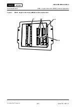
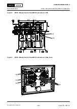
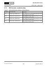
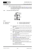
Disconnect the X1 and X3 plugs (002,
).
5
Loosen the cables fixing rail from the module housing (001).
6
Loosen the six screws (003).
NOTE:
Make sure you do not remove them completely.
7
Remove the control module (004) carefully.
8
Attach a “Faulty” label to the control module.
NOTE:
If the part need to be returned to WinGD service station, fill the return sheet
attached to the box of the spare control module.
9
Install the new control module (004).
10
Tighten the six screws (003) to attach the control module to the back plate.
11
Tighten the cable fixing rail to the module housing.
NOTE:
Do not tighten the cable fixing rail too much.
12
Connect the X1 plug to the power supply junction.
13
Connect the X1 and X3 (002) plugs to the control module.
14
Tighten all connectors with two screws.
15
Make sure that the control module must boot-up corrctly.
16
If there is an automatic download, it will show on the control module display.
17
Do a function test of the new control module e.g. valid angle display, related reference pick-
up etc.
18
Make sure that the related reference pickup sensor must go through the new ACM-20
module.
X72-B
AA00-0000-00AAA-200E-A
Operation Manual
WiCE - Angle Control Unit (ACM20) module replacment
Winterthur Gas & Diesel Ltd.
- 296 -
Issue 003 2021-12

