PROCEDURE
1
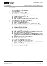
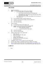
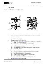
Open the indicator valves in the cylinder covers.
2
Engage the turning gear.
3
Stop the fuel supply to the engine as follows:
3.1
Stop the fuel supply system from the plant.
3.2
Close the shut-off valve at engine connection 49 (fuel inlet).
3.3
Release the pressure in the fuel system.
3.4
Drain the fuel system.
3.5
Close the shut-off valve at engine connection 50 (fuel return outlet).
4
Drain the exhaust gas manifold and the exhaust gas pipe.
5
Stop the air supply to the engine as follows:
5.1
Stop the air supply systems from the plant.
5.2
Close the shut-off valves at engine connection 40 (starting air pipe inlet).
5.3
Turn the hand-wheel of the starting air shut-off valve to the position CLOSED.
5.4
Drain the air systems of the engine.
5.5
Release the pressure in the air pipes.
6
Stop the lubricating oil supply to the engine as follows:
6.1
Stop the oil supply systems from the plant.
6.2
Close the shut-off valves to the engine at engine connection 33 (cylinder oil inlet).
6.3
Set to OFF the control box for the automatic filter.
6.4
If installed, close the shut-off valves to the engine upstream of engine connection
25 (main lubricating oil inlet) and of engine connection 30 (lubricating oil crosshead
inlet).
6.5
Release the pressure in the oil pipes and the oil rail.
6.6
Drain the oil systems of the engine.
7
Stop the cooling water supply to the engine as follows:
7.1
Stop the cooling water supply system from the plant.
7.2
If installed, close the shut-off valves upstream of engine connections 01 and/or 02
(cylinder cooling water inlet).
7.3
Release the pressure in the cooling and wash-water pipes.
7.4
Drain the water systems of the engine.
X72-B
AA00-0000-00AAA-151B-A
Operation Manual
Prepare the engine for standstill or for maintenance
Winterthur Gas & Diesel Ltd.
- 355 -
Issue 003 2021-12


