2
Release the pressure of the servo oil supply unit to 0 bar.
3
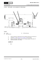
Remove the flange (002.
) from the fuel pump (003).
4
Remove the flange (007) from the intermediate piece (006).
5
Install the HP fuel pipe (001) on to the fuel pump (003). Refer to the Maintenance Manual
for more information.
6
Remove the applicable cover (005) from the supply unit (004).
NOTE:
Make sure that the applicable supply unit cam is at TDC and if not do
.
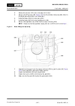
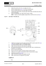
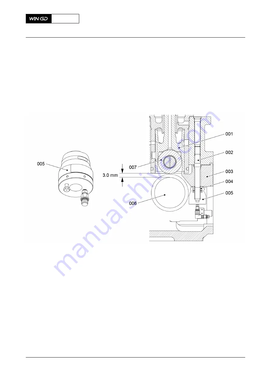
Fig 10-8
Assembly of roller lifter tool
7
Operate the turning gear to turn the supply unit cam at TDC to push the roller (007,
) of the guide piston (001) is at the highest position.
8
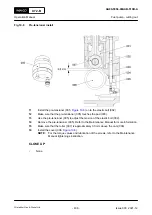
Install the pre-tensioner (005) on to the elastic bolt (004).
9
Make sure that pre-tensioner (005) touches the pad (003).
10
Use the pre-tensioner (005) to loosen the elastic bolt (003). Refer to the Maintenance
Manual for more information.
11
Remove the pre-tensioner(005).
12
Remove the round nut (004), the elastic bolt (002) and the pad (003).
13
Attach the round nut (004) to the elastic bolt (002) on the pad (003) manually.
14
Install the cover (005,
).
15
Make sure that the fuel pump (003) operates correctly.
16
Make sure that the HP fuel pipe (001) has no leaks.
CLOSE UP
•
None
X72-B
AA00-5556-00AAB-730B-A
Operation Manual
Fuel pump - cutting in
Winterthur Gas & Diesel Ltd.
- 443 -
Issue 003 2021-12

