4.2
Cooling water system
The cooling water system supplies the items that follow with cooling water:
•
Cylinder liner
•
Cylinder cover
•
Exhaust valve cages
•
Scavenge air cooler (SAC).
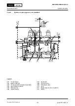
For the schematic diagrams, refer to section
13.1 Schematic diagrams - general
.
The cooling water system has the engine connections as interface to the plant as follows (in
•
Connection 02 (cylinder cooling water inlet)
•
Connection 05 (cylinder liner cooling water inlet (bypass cooling water system)) (optional)
•
Connection 03 (cylinder cooling water outlet)
•
Connection 05 (cylinder cooling water drain outlet)
•
Connection 07 (SAC LT-cooling water inlet) (not shown)
•
Connection 08 (SAC LT-cooling water outlet) (not shown).
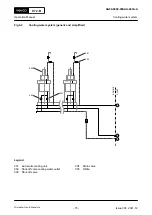
If the supply at the engine connection 02 is installed, the cylinder liner is supplied with cooling
water at a higher temperature than the cylinder cover.
The cooling water system has the parts that follow:
•
Automatic venting unit
The automatic venting unit (001) constantly releases unwanted air from the cooling water.
•
Shut-off valve
The shut-off valve (002) and (003) constantly releases cooling water to the automatic
venting unit (001) to release unwanted air from the cooling water.
•
Drain valve
The drain valve (004) is used to drain the cooling water.
X72-B
AA00-0000-00AAA-043A-A
Operation Manual
Cooling water system
Winterthur Gas & Diesel Ltd.
- 74 -
Issue 003 2021-12


