WORKSHOP MANUAL
Winget Mechanically Fed Mixers
Models: 200TM
From 1998
EC machines, which are “CE”, marked are fitted with a hose burst valve to protect the
operator in the event of a hose failing.
The valve are pre-set on leaving the factory fitted to a machine but occasionally
require adjusting as they wear in service. To adjust, ensure the hopper is lowered
and any residual hydraulic pressure has been dissipated by operating the control
lever a number of times with the engine/motor stopped. Remove the valve from the
ram noting which way round it was installed, the body is marked. Unscrew the inner
baffle assembly, noting which way it was installed and adjust the baffles by holding
the nut and turning the capscrew with a hexagon key until the gap between the
baffles measures 0.889mm.
The valve should then be re-assembled and screwed onto the ram, ensuring the
valve is the correct way round. Fit the hydraulic adapter and bonded seal coating the
threads with hydraulic sealer. See Service Bulletin in SB100 for further details on the
valve.
Note, position the assembled ram into the mainframe so that the fitting/hose burst
valve face the L/H side (hopper cradle) of the mainframe.
New valves supplied or received as a spares item should be dismantled before fitting
and the inner baffles adjusted by holding the nut and turning the capscrew with an
hexagon key until the gap between the baffles measures 0.889mm.
It is quite common for machines fitted with hose burst valves to ‘lock out’ in service
with the result that a raised hopper will not lower. Operating the control lever in a
‘violent’ manner to shake material free is the major cause of ‘lock outs.’ To release a
‘locked out’ hose burst valve slowly and gently operate the control lever to raise the
hopper, this will blow off the ‘locked out’ valve allowing the hopper to be gently
lowered approximately 150mm following which the hopper can be used as normal.
Hydraulic Tank
The hydraulic tank is mounted below the cover on the side of the engine housing. To
gain access to the suction strainer or clean the filler breather it will be necessary to
remove the cover and the open up the tank via the removable circular cover located
on top of the tank.
The suction strainer is screwed onto the suction fitting inside the tank and should be
removed and cleaned in accordance with the service schedules. A drain plug is
provided below the tank assisting oil changes, and the tank can be quickly removed
should it be necessary to steam or pressure clean out.
Hopper Removal
The hopper is retained to the cradle by means of a number of ‘coach bolts’. To
remove fully lower the hopper, attach suitable lifting equipment to the hopper lifting
points, remove the coach bolts and lift the hopper clear.
Summary of Contents for 200TM
Page 3: ...WORKSHOP MANUAL 200TM SECTION 1 INTRODUCTION...
Page 6: ...WORKSHOP MANUAL 200TM SECTION 2 REPAIR SERVICE PROCEDURES...
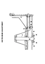
Page 12: ...200TM DRUM ADJUSTMENT...
Page 42: ...WORKSHOP MANUAL 200TM SECTION 3 GENERAL ARRANGEMENT DIMENSIONS...
Page 43: ...GENERAL ARRANGEMENT...
Page 44: ...DIMENSIONS...
Page 45: ...WORKSHOP MANUAL 200TM SECTION 4 SERVICE SCHEDULES LUBRICATION DIAGRAM...
Page 48: ...LUBRICATION POINTS...
Page 49: ...LUBRICANTS...
Page 50: ...WORKSHOP MANUAL 200TM SECTION 5 HYDRAULIC CIRCUIT DIAGRAMS...
Page 51: ...200TM LATER BASIC HYDRAULIC CIRCUIT...
Page 52: ...200TM LATER DRAGLINE BATCHWEIGER HYDRAULIC CIRCUIT...
Page 53: ...WORKSHOP MANUAL 200TM SECTION 6 WIRING DIAGRAMS...
Page 59: ...Hourmeter lamp dwg 04 03 02 12 50 36 Scaled to fit...
Page 60: ...Hourmeter no lamp dwg 04 03 02 12 53 33 Scaled to fit...
Page 62: ...WORKSHOP MANUAL 200TM SECTION 7 NOISE LEVELS...
Page 64: ...WORKSHOP MANUAL 200TM SECTION 8 SPECIAL TOOLS...
Page 65: ...200TM PUNCH VALVE SEAT 200TM SPECIAL TOOL V2003698 CASE HARDEN TO 45 50 ROCKWELL...
Page 66: ...200TM DRUM BLADE DRILLING GUIDE SPECIAL TOOL 200TM 513360100...
Page 67: ...200TM SPECIAL TOOLS...
Page 68: ...1 513204000 CLAMP DRUM CLIP 1 2 V2003698 PUNCH BLEED VALVE SEAT 1 200TM SPECIAL TOOLS...
Page 69: ...WORKSHOP MANUAL 200TM SECTION 9 HYDRAULIC CONTROL VALVE SERVICE MANUAL...
Page 70: ...PAGE INTENTIONALLY BLANK...
Page 71: ...WORKSHOP MANUAL 200TM SECTION 10 PARTS LISTINGS...
Page 73: ...200TM MAINFRAME AXLES AND STABILISERS...
Page 90: ...200TM 415 VOLT START STOP SWITCH STAR DELTA...
Page 92: ...200TM 415 VOLT START STOP SWITCH DIRECT ON LINE...
Page 98: ...200TM HOPPER...
Page 110: ...200TM WATER TANK FIT SPECIAL WASHER V2004220 BETWEEN ITEMS 11 12...
Page 114: ...200TM DYNAMO AND MOUNTING LISTER PETTER TS1 HS...
Page 118: ...200TM DRAGLINE ASSEMBLY...
Page 120: ...200TM DRAGLINE ASSEMBLY...
Page 124: ...200TM DRAGLINE SHOVEL...
Page 126: ...200TM DRAGLINE FEEDAPRON...
Page 130: ...200TM LISTER PETTER TS1 ELECTRIC START...
Page 132: ...200TM DECALS AND LOGOS 1 2 3 4 5 6 7 8 9 10 11 12 13 14 15 16 17 18 19 20 21 22...
Page 134: ...200TM DECALS AND LOGOS 23 24 25 26 27 28 29...
Page 135: ...200TM SPECIAL TOOLS...
Page 136: ...1 513204000 CLAMP DRUM CLIP 1 2 V2003698 PUNCH BLEED VALVE SEAT 1 200TM SPECIAL TOOLS...
Page 137: ...WORKSHOP MANUAL 200TM SECTION 11 BATCHWEIGHER MAINTENANCE INSTRUCTIONS...
Page 138: ...MAINTENANCE INSTRUCTIONS HYDRAULIC WEIGHING UNITS WWW WINGET CO UK...
Page 140: ......
Page 141: ......
Page 142: ......
Page 143: ......
Page 144: ......
Page 145: ......
Page 146: ......
Page 147: ......

