


WORKSHOP MANUAL
Winget Mechanically Fed Mixers
Models: 200TM
From 1998
If a dragline or batchweigher is to be installed information on the control block,
solenoid or bleed valve can be found later in this manual as can a detailed
description of the hydraulic system.
Engine TS/TR1 Hand Start
“CE” marked machines are fitted with an extended engine oil drainpipe and ‘anti-kick
back starting handles’ in order to comply with local legislation. For information on the
starting handles refer to the engine operators handbook or engine workshop manual.
For details on engine services or overhauls, changing engine oils, filters and bleeding
the fuel system refer to the engine operator’s handbook or engine workshop manual.
Note, the engine is set to run at 1500 rpm and rotates Anti-clockwise at the flywheel
end.
Drive Sprocket Removal/Replacement
The drive sprocket is mounted onto flywheel end extension shaft, approximately
40mm from the end of the shaft and is secured with a gib head key and grubscrew.
To remove the sprocket, first remove the engine housing closing and top plate,
exhaust extension pipe, upper and lower chain guard, drive chain and engine
housing support bracket, If a dragline option is fitted remove the dynamo drive belt.
Remove the four bolts securing the engine to the bed and slide the engine backward
allowing access to the extension shaft. Turn the flywheel until the key and grubscrew
are visible. Mark the position of the sprocket on the shaft and remove the grubscrew
and key, tapping the sprocket backward on the shaft away from the key will assist in
the removal of the key.
Smear the bore of the new sprocket with anti-seize compound and slide onto the
shaft upto the mark made earlier. Fit the key and grubscrew, due to manufacturing
differences it may be necessary to fit a new key. Reposition the engine, refit the bolts
and drive chain, if a dragline is fitted slip the dynamo drive belt over the shaft and
sprocket onto the pulley before fitting the chain, confirm the chain is correctly aligned
and check the chain tension.
The chain tension is correct when the chain deflects approximately 5mm about the
centre line, the deflection should be checked midway between the lower sprocket and
upper chainwheel.
Add or subtract shims below the engine to correctly tension the chain.
A chain running too tight will cause starting problems and the increased loadings will
increase the rate of wear on the chain and sprocket and may also damage the
Summary of Contents for 200TM
Page 3: ...WORKSHOP MANUAL 200TM SECTION 1 INTRODUCTION...
Page 6: ...WORKSHOP MANUAL 200TM SECTION 2 REPAIR SERVICE PROCEDURES...
Page 12: ...200TM DRUM ADJUSTMENT...
Page 42: ...WORKSHOP MANUAL 200TM SECTION 3 GENERAL ARRANGEMENT DIMENSIONS...
Page 43: ...GENERAL ARRANGEMENT...
Page 44: ...DIMENSIONS...
Page 45: ...WORKSHOP MANUAL 200TM SECTION 4 SERVICE SCHEDULES LUBRICATION DIAGRAM...
Page 48: ...LUBRICATION POINTS...
Page 49: ...LUBRICANTS...
Page 50: ...WORKSHOP MANUAL 200TM SECTION 5 HYDRAULIC CIRCUIT DIAGRAMS...
Page 51: ...200TM LATER BASIC HYDRAULIC CIRCUIT...
Page 52: ...200TM LATER DRAGLINE BATCHWEIGER HYDRAULIC CIRCUIT...
Page 53: ...WORKSHOP MANUAL 200TM SECTION 6 WIRING DIAGRAMS...
Page 59: ...Hourmeter lamp dwg 04 03 02 12 50 36 Scaled to fit...
Page 60: ...Hourmeter no lamp dwg 04 03 02 12 53 33 Scaled to fit...
Page 62: ...WORKSHOP MANUAL 200TM SECTION 7 NOISE LEVELS...
Page 64: ...WORKSHOP MANUAL 200TM SECTION 8 SPECIAL TOOLS...
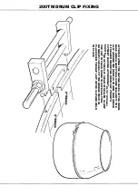
Page 65: ...200TM PUNCH VALVE SEAT 200TM SPECIAL TOOL V2003698 CASE HARDEN TO 45 50 ROCKWELL...
Page 66: ...200TM DRUM BLADE DRILLING GUIDE SPECIAL TOOL 200TM 513360100...
Page 67: ...200TM SPECIAL TOOLS...
Page 68: ...1 513204000 CLAMP DRUM CLIP 1 2 V2003698 PUNCH BLEED VALVE SEAT 1 200TM SPECIAL TOOLS...
Page 69: ...WORKSHOP MANUAL 200TM SECTION 9 HYDRAULIC CONTROL VALVE SERVICE MANUAL...
Page 70: ...PAGE INTENTIONALLY BLANK...
Page 71: ...WORKSHOP MANUAL 200TM SECTION 10 PARTS LISTINGS...
Page 73: ...200TM MAINFRAME AXLES AND STABILISERS...
Page 90: ...200TM 415 VOLT START STOP SWITCH STAR DELTA...
Page 92: ...200TM 415 VOLT START STOP SWITCH DIRECT ON LINE...
Page 98: ...200TM HOPPER...
Page 110: ...200TM WATER TANK FIT SPECIAL WASHER V2004220 BETWEEN ITEMS 11 12...
Page 114: ...200TM DYNAMO AND MOUNTING LISTER PETTER TS1 HS...
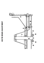
Page 118: ...200TM DRAGLINE ASSEMBLY...
Page 120: ...200TM DRAGLINE ASSEMBLY...
Page 124: ...200TM DRAGLINE SHOVEL...
Page 126: ...200TM DRAGLINE FEEDAPRON...
Page 130: ...200TM LISTER PETTER TS1 ELECTRIC START...
Page 132: ...200TM DECALS AND LOGOS 1 2 3 4 5 6 7 8 9 10 11 12 13 14 15 16 17 18 19 20 21 22...
Page 134: ...200TM DECALS AND LOGOS 23 24 25 26 27 28 29...
Page 135: ...200TM SPECIAL TOOLS...
Page 136: ...1 513204000 CLAMP DRUM CLIP 1 2 V2003698 PUNCH BLEED VALVE SEAT 1 200TM SPECIAL TOOLS...
Page 137: ...WORKSHOP MANUAL 200TM SECTION 11 BATCHWEIGHER MAINTENANCE INSTRUCTIONS...
Page 138: ...MAINTENANCE INSTRUCTIONS HYDRAULIC WEIGHING UNITS WWW WINGET CO UK...
Page 140: ......
Page 141: ......
Page 142: ......
Page 143: ......
Page 144: ......
Page 145: ......
Page 146: ......
Page 147: ......


