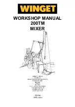
WORKSHOP MANUAL
Winget Mechanically Fed Mixers
Models: 200TM
From 1998
Introduction
It is assumed that Personnel involved in either the Assembly or repair of Winget
Mixers will be familiar with the product, either through the operation of, or previous
repair and maintenance work. It is not intended to be used by Personnel who are
neither familiar with the product or mechanically inexperienced.
It is also assumed that personnel are aware of the Health and Safety Regulations,
which should be applied to all working practices, but the following should act as a
reminder.
Ensure all work tools are in good condition.
Always wear Safety Spectacles when using Soft or Hard Faced Hammers, Chisels or
when using Air Tools. Wear Safety Spectacles when cleaning Hardened Concrete or
Mortar off components.
Do not misuse Air Lines and be aware of the damage Compressed Air can cause if
misused.
Always make sure Lifting Equipment is in good condition and the Safe Working
Loads exceed the weights of the components to be lifted.
Oils, Fuels, Silicone Sealer and Open Gear Lubricants can cause skin diseases if
allowed to contaminate the skin. Always apply barrier creams, wear suitable
protective clothing or when contamination is unavoidable clean the area with soap
and water as soon as possible. Do not use thinners or other solvents to clean skin.
Health and Safety is a matter of common sense. If common sense is applied
correctly Health and Safety can be improved upon and the risk of accidents reduced.
L/H and R/H views are taken when standing directly behind and facing the engine
housing.
Whilst every effort is made to ensure the contents of this manual are accurate,
Winget Limited accept no responsibility for errors or omissions and reserve the right
to alter specification without prior notification and certain sections may then no longer
apply.
Repair & Maintenance Procedures
The following procedures are based in part on the procedures issued to Distributors
and the instructions should be used in conjunction with the appropriate Parts and
Operators Manual or Parts Microfiche. Reference should also be made to the Parts
Listings in Section 10 for a guide to the correct sequence for assembling components
and sub assemblies.
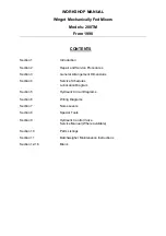
Summary of Contents for 200TM
Page 3: ...WORKSHOP MANUAL 200TM SECTION 1 INTRODUCTION...
Page 6: ...WORKSHOP MANUAL 200TM SECTION 2 REPAIR SERVICE PROCEDURES...
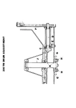
Page 12: ...200TM DRUM ADJUSTMENT...
Page 42: ...WORKSHOP MANUAL 200TM SECTION 3 GENERAL ARRANGEMENT DIMENSIONS...
Page 43: ...GENERAL ARRANGEMENT...
Page 44: ...DIMENSIONS...
Page 45: ...WORKSHOP MANUAL 200TM SECTION 4 SERVICE SCHEDULES LUBRICATION DIAGRAM...
Page 48: ...LUBRICATION POINTS...
Page 49: ...LUBRICANTS...
Page 50: ...WORKSHOP MANUAL 200TM SECTION 5 HYDRAULIC CIRCUIT DIAGRAMS...
Page 51: ...200TM LATER BASIC HYDRAULIC CIRCUIT...
Page 52: ...200TM LATER DRAGLINE BATCHWEIGER HYDRAULIC CIRCUIT...
Page 53: ...WORKSHOP MANUAL 200TM SECTION 6 WIRING DIAGRAMS...
Page 59: ...Hourmeter lamp dwg 04 03 02 12 50 36 Scaled to fit...
Page 60: ...Hourmeter no lamp dwg 04 03 02 12 53 33 Scaled to fit...
Page 62: ...WORKSHOP MANUAL 200TM SECTION 7 NOISE LEVELS...
Page 64: ...WORKSHOP MANUAL 200TM SECTION 8 SPECIAL TOOLS...
Page 65: ...200TM PUNCH VALVE SEAT 200TM SPECIAL TOOL V2003698 CASE HARDEN TO 45 50 ROCKWELL...
Page 66: ...200TM DRUM BLADE DRILLING GUIDE SPECIAL TOOL 200TM 513360100...
Page 67: ...200TM SPECIAL TOOLS...
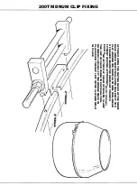
Page 68: ...1 513204000 CLAMP DRUM CLIP 1 2 V2003698 PUNCH BLEED VALVE SEAT 1 200TM SPECIAL TOOLS...
Page 69: ...WORKSHOP MANUAL 200TM SECTION 9 HYDRAULIC CONTROL VALVE SERVICE MANUAL...
Page 70: ...PAGE INTENTIONALLY BLANK...
Page 71: ...WORKSHOP MANUAL 200TM SECTION 10 PARTS LISTINGS...
Page 73: ...200TM MAINFRAME AXLES AND STABILISERS...
Page 90: ...200TM 415 VOLT START STOP SWITCH STAR DELTA...
Page 92: ...200TM 415 VOLT START STOP SWITCH DIRECT ON LINE...
Page 98: ...200TM HOPPER...
Page 110: ...200TM WATER TANK FIT SPECIAL WASHER V2004220 BETWEEN ITEMS 11 12...
Page 114: ...200TM DYNAMO AND MOUNTING LISTER PETTER TS1 HS...
Page 118: ...200TM DRAGLINE ASSEMBLY...
Page 120: ...200TM DRAGLINE ASSEMBLY...
Page 124: ...200TM DRAGLINE SHOVEL...
Page 126: ...200TM DRAGLINE FEEDAPRON...
Page 130: ...200TM LISTER PETTER TS1 ELECTRIC START...
Page 132: ...200TM DECALS AND LOGOS 1 2 3 4 5 6 7 8 9 10 11 12 13 14 15 16 17 18 19 20 21 22...
Page 134: ...200TM DECALS AND LOGOS 23 24 25 26 27 28 29...
Page 135: ...200TM SPECIAL TOOLS...
Page 136: ...1 513204000 CLAMP DRUM CLIP 1 2 V2003698 PUNCH BLEED VALVE SEAT 1 200TM SPECIAL TOOLS...
Page 137: ...WORKSHOP MANUAL 200TM SECTION 11 BATCHWEIGHER MAINTENANCE INSTRUCTIONS...
Page 138: ...MAINTENANCE INSTRUCTIONS HYDRAULIC WEIGHING UNITS WWW WINGET CO UK...
Page 140: ......
Page 141: ......
Page 142: ......
Page 143: ......
Page 144: ......
Page 145: ......
Page 146: ......
Page 147: ......

