background image

                             OPERATION  (‘HL’ Model)                   12A

Never

 commence work until the daily service checks have been

carried out.

Only 

tip or discharge the skip or raise the scissors on level ground.

The hydraulic system control valve and operating levers are mounted
on top of the hydraulic tank on the left-hand side of the machine.

The inner lever controls the scissor operation whilst the outer lever
controls the skip tipping functions, the function of each lever is
indicated on the decal on the rear of the valve mounting plate.

The operating levers have three positions, forwards for ‘Scissor Lift’
or ‘Skip Tip’, centre for ‘Neutral’ or ‘Hold’ and rearwards for ‘Scissor
Lower’ or ‘Skip Return’.

The hydraulics will not operate until the engine is running, although
it is possible to lower a raised skip or scissors without engine power
by moving the operating levers to the ‘Dump’ or ‘Lower’ positions.
For this reason the machine should not be left unattended with either
the skip or scissors raised. Refer to the Honda HP500H Operators
Handbook for instructions on starting the engine.

With the engine running and the engine speed set to fast idle, refer to
the decal on the rear of the valve mounting plate and identify the
lever controlling the function required, slowly push the lever
forwards. The rate of oil delivered to the skip tipping or scissor ram
and therefore the speed at which the skip tips or the scissors lift is
proportional both to the distance the lever is moved and the speed at
which the engine is set.

Holding the lever forwards until the skip or scissors reaches the
maximum travel of the ram will cause the relief valve located in the
control valve to ‘blow off’ allowing the oil to return to tank. Do not
hold the lever forward when the ‘relief valve’ blows, this will cause
the hydraulic oil temperature to increase and may cause damage to
components. Once the ram reaches the end of its travel release the
lever to the neutral or hold position.

Releasing the operating lever will allow it to automatically return to
neutral position and movement of the skip or scissors will stop, even
if the ram has not reached the full extent of its travel, or the skip is

Summary of Contents for TD500

Page 1: ...NDBOOK TD500 TD500HL TRACKED DUMPER WINGET LIMITED PO BOX 41 EDGEFOLD INDUSTRIAL ESTATE PLODDER LANE BOLTON LANCS BL4 0LR Tel 44 0 1204 854650 parts winget co uk service winget co uk www winget co uk ISSUE 13 2020 ...

Page 2: ......

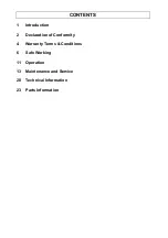
Page 3: ...CONTENTS 1 Introduction 2 Declaration of Conformity 4 Warranty Terms Conditions 6 Safe Working 11 Operation 13 Maintenance and Service 20 Technical Information 23 Parts Information ...

Page 4: ......

Page 5: ...lthough correct at the time of publication may be subject to alteration by the manufacturers without notice Winget Limited operates a policy of continuous product development Therefore some illustrations or text within this publication may differ from your machine WARNING The operator must read both this handbook and the Honda publication and be familiar with all the controls before attempting to ...

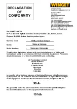
Page 6: ...ith the Conformity Assessment Procedure detailed in Annexe VI of Directive 2000 14 EC and verified by AV Technology Limited AVTECH House Birdhall Lane Cheadle Heath Stockport Cheshire SK3 OXU is in conformity with the provisions of the Noise Emission in the Environment by Equipment for use Outdoors Directive 2000 14 EC A representative sample of this equipment was tested and Sound Power Levels Lwa...

Page 7: ...king of authorised person Joint Managing Director Position The above named person is also responsible for holding the Technical Documentation applicable to the product to which this declaration relates and may be contacted at the address which appears at the head of this declaration Please take care of this document as duplicate copies are not available This document is in accordance with EN45014 ...

Page 8: ...ury resulting directly or indirectly from any defect in the goods Items not covered by Warranty and considered to be the customers responsibility include normal maintenance services replacement of service items and consumables replacement required due to abuse accident misuse or improper operation replacement of wearable items e g pins bushes etc All Warranty repairs on the Honda HP500H Power Carr...

Page 9: ...id down in this handbook by Winget Limited Evidence that these have been complied with may be required before Warranty claims are reimbursed Winget Limited have a policy of continuous product improvement and reserve the right to change specifications without notice No responsibility will be accepted for discrepancies which may occur between the specification of machines and the descriptions contai...

Page 10: ...ls It was not designed to carry any loads or materials that may over hang the skip in any way nor was it designed to carry loads that may move around in the skip uncontrollably If in doubt as to the suitability of this machine for a particular task refer to Winget Limited or Honda Power Equipment Never commence work until the daily service checks have made carried out Always report faults as soon ...

Page 11: ... is stationary and the clutch levers have been released Never exceed the rated payload this machine is designed to carry 500kg on level ground this should be reduced to 350kg when operating on gradients Never operate on any downward gradient which exceeds 15 o or on any upward gradient which exceeds 20 o Always walk behind the machine on gradients never in front of it do not reverse down gradients...

Page 12: ...sure from the hydraulic system before carrying out any kind of maintenance or adjustment Never allow unqualified personnel to attempt to repair remove or replace any part of the machine Always obtain advice before mixing oils some are incompatible if in doubt completely drain flush and refill Many liquids used in this machine are harmful if taken internally or splashed into the eyes In the event o...

Page 13: ...or fuels come into contact with the skin Always store fuels in small quantities in the correct specially designed containers which can be securely fastened Store fuel in a cool well ventilated store away from sources of ignition Always ensure that any Warning Safety or Advisory Decals attached to the machine are legible and clean replace if damaged defaced or missing ...

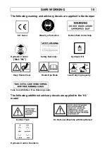
Page 14: ... Not Work Under Skip Hydraulic Control Safety Reminder Hydraulic Oil Not HL Keep Hands Clear Reads Ops Book Load Carrying Capacity Take Care With Non Free Running Loads The following additional advisory decals are applied to the HL model Do Not Track Do Not Leave Machine with Skip Raised Hydraulic Control Functions ...

Page 15: ... skip tipping ram and therefore the speed at which the skip tips is proportional both to the distance the lever is moved and the speed at which the engine is set Holding the lever forwards until the skip reaches the maximum travel of the ram will cause the relief valve located in the control valve to blow off allowing the oil to return to tank Do not hold the lever forward when the relief valve bl...

Page 16: ...the machine Holding the lever to the rear until the skip is fully lowered will cause the relief valve located in the control valve to blow off allowing the oil to return to tank Do not continue to hold the lever rearward when the relief valve blows off this will cause the hydraulic oil temperature to increase and may cause damage to components Once the skip is seated on the stops release the opera...

Page 17: ...the Honda HP500H Operators Handbook for instructions on starting the engine With the engine running and the engine speed set to fast idle refer to the decal on the rear of the valve mounting plate and identify the lever controlling the function required slowly push the lever forwards The rate of oil delivered to the skip tipping or scissor ram and therefore the speed at which the skip tips or the ...

Page 18: ... lever and gently bring the skip back onto to stops or lower the scissors to the rest position This is particularly important if you have not completely emptied the skip Allowing the skip or scissors to return onto the stops or rest position with force will damage the machine Holding the lever to the rear until the skip or scissors are fully lowered will cause the relief valve located in the contr...

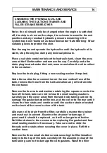
Page 19: ...ration more frequently in dusty dirty conditions Change the hydraulic oil clean the hydraulic oil filter strainer Clean the hydraulic oil filler strainer breather assembly Note the oil level should only be checked when the engine is switched off the skip is at rest on the stops the scissors lowered to the rest position and any residual hydraulic pressure remaining in the system has been dumped as ...

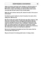
Page 20: ...e tank remove the hose from the tank and allow any oil to drain into the container Remove the four nuts and washers retaining the square cover to the face of the tank take care not to lose the small sealing washers Carefully pull the cover away from the tank body taking care not to damage the gasket between the two pull the cover to the rear until it clears the four studs and continue until the su...

Page 21: ...ight glass Refit the cap Start the engine and operate the hydraulic operating lever s in both directions a number of times raising and lowering the skip and scissors to purge the system of air Bring the skip back onto the stops and lower the scissors to the rest position Stop the engine dump any residual pressure remaining in the hydraulic system Check the level of the oil in the sight glass and t...

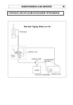
Page 22: ...MAINTENANCE AND SERVICE 16 Standard Tipping Model not HL HYDRAULIC CIRCUIT DIAGRAM STANDARD TIPPING MODEL ...

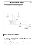
Page 23: ...ing and lowering The system comprises of the following main components TANK the tank is filled through a filler strainer the cap for which incorporates a breather In the base of the tank accessed via the end plate is a washable suction strainer HYDRAULIC CIRCUIT DIAGRAM HL MODEL HYDRAULIC CIRCUIT DESCRIPTION ...

Page 24: ...ssive pressure from damaging the hydraulic pump and other components TIPPING RAM the single tipping ram is of the double acting type oil enters the lower part of the cylinder full bore when the operating lever is moved forwards and pushes the piston and rod out of the cylinder tipping the skip When the lever is moved to the rear oil enters the upper part of the cylinder annulus and pushes the pist...

Page 25: ...ic pressure is correct as follows Fit a 0 3000 psi 0 207bar pressure gauge into the hydraulic system at the base of the tipping ram or scissor ram or if more accessible at one of the hose connection to the control valve using a tee piece and short length of suitable hydraulic hose Start the engine move the lever to activate the circuit into which the gauge was fitted and check the reading on the g...

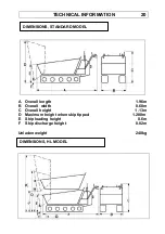
Page 26: ...verall length 1 96m B Overall width 0 68m C Overall height 1 13m D Maximum height when skip tipped 1 280m E Skip loading height 0 6m F Skip discharge height 0 02m Unladen weight 240kg DIMENSIONS STANDARD MODEL DIMENSIONS HL MODEL ...

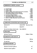
Page 27: ... raised 1 290m J Skip discharge height scissors raised 1 220m K Maximum height skip raised scissors raised 2 460m Unladen weight 317kg Hydraulic Oil Azzola ZS46 Capacity 5 litres Grease Multis EP2 General lubricating oil pivot pins Rubia B20W 30 Hydraulic Pressure 2500psi 172 bar On level ground 500kgs On gradients 350kgs Maximum Downward gradient 15 o Maximum Upward gradient 20 o LUBRICANTS CAPAC...

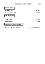
Page 28: ...L INFORMATION 22 Operators Ear 85LPA Directive 2000 14 EC 101LWA Forward travel 0 4 3 km h Reverse travel 0 3 6 km h Hand Arm Vibration EN1033 11 m s2 3600 rpm NOISE LEVELS TRAVEL SPEED VIBRATION AT HANDLEBARS ...

Page 29: ...PARTS INFORMATION 23 TD500 TD500HL PARTS SECTION ...

Page 30: ......

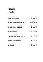
Page 31: ...TD500 Parts SKIP CHASSIS 1 A 1 HANDLEBAR SUPPORT RH 1 A 1A HYDRAULIC CIRCUIT 2 A 1 RAM TIPPING 2 A 2 TANK CONTROL VALVE 3 A 1 PUMP COUPLING 4 A 1 DECALS 5 A 1 ...

Page 32: ......

Page 33: ...1 A 1 TD500 Dumper ...

Page 34: ...N ram body 1 6 267S09 WASHER flat 4 7 44S16J PIN split 4 10 V2005340 PIN skip pivot 1 11 7S02 NUT 1 12 17S03 WASHER spring 1 13 267S04 WASHER flat 1 14 8S02D BOLT 1 15 11S04D SCREW set 4 16 267S06 WASHER flat 8 17 17S05 WASHER spring 4 18 7S04 NUT 4 20 11S03C SCREW set 2 21 267S05 WASHER flat 2 22 17S04 WASHER spring 2 25 131S04 NIPPLE grease 1 26 176S01 CAP grease nipple 1 ...

Page 35: ...1 A 1A TD500 Dumper ...

Page 36: ...EBAR SUPPORT RH 1 A 1A Item Part no Serial no Description Qty 1 V2005765 mid 07 Onwards SUPPORT Handlebar R H 1 2 153S01 U CLAMP 29mm 2 3 153S02 U CLAMP 32mm 1 4 267S05 WASHER Flat 6 5 17S04 WASHER Spring 6 ...

Page 37: ...2 A 1 TD500 Dumper ...

Page 38: ... control valve return to tank 1 6 122S03 ADAPTOR male male 4 6A 119S03 ADAPTOR male male 1 7 100S03 SEAL bonded 6 7A 100S02 SEAL bonded 1 8 119S03 ADAPTOR male male 2 9 PLUG blanking 2 10 122S02 ADAPTOR male male 2 11 100S02 SEAL bonded 2 12 154S01 ADAPTOR tee 1 13 120S01 CAP blanking 1 15 V2005330 RAM skip tipping see page 2 A 2 1 16 V603013 BUSH 4 19 PUMP hydraulic see page 4 A 1 1 20 TANK see p...

Page 39: ...2 A 2 TD500 Dumper ...

Page 40: ...Part no Serial no Description Qty 1 V2005330 RAM skip tipping assembly 1 2 V603576 GLAND cylinder 1 3 V603577 CYLINDER ram 1 4 V603578 ROD piston 1 5 V603578 SCREW grub 1 6 V603580 PISTON 1 7 V603013 BUSH 4 10 V603574 KIT seals 1 ...

Page 41: ...3 A 1 TD500 Dumper ...

Page 42: ...3685 END CAP SPRING KIT 4 bolt 1 2 8S03H BOLT 2 3 267S05 WASHER flat 4 4 17S04 WASHER spring 2 5 7S03 NUT 2 10 V2005359 FILLER BREATHER 1 11 68S02A SCREW slotted head 3 15 V2005347 TANK hydraulic 1 15A 153S01 Clamp U Bolt not illustrated 1 16 11S03C SCREW set 2 17 17S04 WASHER spring 2 18 267S05 WASHER flat 2 20 411411135 STUD 1 21 267S06 WASHER flat 1 22 17S05 WASHER spring 1 23 324S04 NUT 1 25 V...

Page 43: ...4 A 1 TD500 Dumper ...

Page 44: ...engine parts catalogue 1 18 WASHER see engine parts catalogue 1 19 V2005345 1593 19 V603661 1594 COUPLING engine 53mm dia KTR 1 20 V2005344 PULLEY 1 21 305110550 KEY parallel 1 see note below 25 V2005365 GUARD belt drive 1 26 V2005367 PLATE 1 27 V2005366 FLANGE guard 1 28 101S05B RIVET 4 30 V2005589 GUARD engine 1 31 101S05D RIVET 2 COUPLING engine 55mm dia UCC Parker 1 Note Up to Serial numbers 1...

Page 45: ...5 A 1 TD500 Dumper ...

Page 46: ... DECAL hydraulic oil 1 8 V2005311 DECAL noise LWA 101 1 9 V2004131 DECAL noise 85 LPA 1 10 10284A01 DECAL dump return 1 11 10536A02 DECAL tipping non free running loads 1 12 504694600 DECAL safety warning 1 13 DM157 DECAL do not work under skip 1 14 V2003037 PLATE serial number Winget 1 101S05D RIVET for serial number plate 4 15 V2004223 DECAL CE mark 1 16 V2004281 DECAL chain drive 1 17 JDD8089 P...

Page 47: ...s SKIP MOUNTING FRAME 1 A 1 HANDLEBAR SUPPORT RH 1 A 1A SCISSOR CHASSIS 1 A 2 HYDRAULIC CIRCUIT 2 A 1 CONTROL VALVE 2 B 1 TANK hydraulic 2 C 1 RAMS scissors lift skip tipping 2 R 1 PUMP COUPLING 3 A 1 DECALS 4 A 1 ...

Page 48: ......

Page 49: ...1 A 1 TD500HL Dumper ...

Page 50: ... 1 5 V2005342 PIN ram body 1 6 267S09 WASHER flat 4 7 44S16J PIN split 4 10 V2005423 PIN skip pivot 1 11 V2005403 PIN lynch 2 15 11S05K SCREW set 2 16 7S05 NUT 4 17 17S06 WASHER spring 2 20 187S08EE CLAMP hose 1 21 68S04F SCREW cap head 1 22 267S05 WASHER flat 1 24 61S03 NUT Binx self locking 1 25 SB1321 SUPPORT skip 1 26 V601147 PIN feather R clip 2 October 2003 Serial no ...

Page 51: ...1 A 1A TD500HL Dumper ...

Page 52: ...EBAR SUPPORT RH 1 A 1A Item Part no Serial no Description Qty 1 V2005765 mid 07 Onwards SUPPORT Handlebar R H 1 2 153S01 U CLAMP 29mm 2 3 153S02 U CLAMP 32mm 1 4 267S05 WASHER Flat 6 5 17S04 WASHER Spring 6 ...

Page 53: ...1 A 2 TD500HL Dumper ...

Page 54: ...or lower pivot 1 7 V2005403 PIN lynch 4 8 131S02 NIPPLE grease 1 9 176S01 CAP grease nipple 1 15 V2005330 RAM scissor lift see page 2 R 1 2 16 V2005408 PIN ram eye 1 17 V2005401 PIN ram cylinder 1 18 44S03F PIN split 2 19 44S16J PIN split 2 19A 267S07 WASHER flat 2 20 V2005392 CHASSIS subframe 1 21 11S04D SCREW set 8 22 267S06 WASHER flat 16 23 17S05 WASHER spring 8 24 7S04 6 25 59S03 NUT Nyloc se...

Page 55: ...2 A 1 TD500HL Dumper ...

Page 56: ...EAL bonded 1 10 V2005330 RAM scissor lift see page 2 R 1 1 11 100S02 SEAL bonded 2 12 122S02 ADAPTOR male male 2 13 319S01D HOSE control valve to scissor lift 1 14 53S01J HOSE control valve to scissor lower 1 15 V2005397 RAM skip tipping see page 2 R 1 1 16 318S01D HOSE control valve to skip tip 1 17 318S01M HOSE control valve to skip lower 1 19 PUMP hydraulic see page 3 A 1 1 20 V2003253 STRAP ny...

Page 57: ...2 B 1 TD500HL Dumper ...

Page 58: ...c w lever 1 3 V603573 LEVER 1 V603592 KIT seals 1 V603593 VALVE relief 1 5 100S04 SEAL bonded 3 6 127S04 PLUG hex head 3 10 100S04 SEAL bonded 2 11 119S08 ADAPTOR male male 2 12 100S03 SEAL bonded 4 13 119S03 ADAPTOR male male 2 14 93S08 ADAPTOR bulkhead 2 15 154S01 ADAPTOR tee 1 16 120S01 CAP blanking 1 October 2004 ...

Page 59: ...2 C 1 TD500HL Dumper ...

Page 60: ... illustrated 1 16 11S03C SCREW set 2 17 17S04 WASHER spring 2 18 267S05 WASHER flat 2 20 411411135 STUD 1 21 267S06 WASHER flat 1 22 17S05 WASHER spring 1 23 324S04 NUT 1 25 V2005355 FILTER suction 1 26 V2005356 GASKET filter mounting plate 1 27 V2005360 PLATE filter mounting 1 28 267S04 WASHER flat 4 29 17S03 WASHER spring 4 30 7S02 NUT 4 31 186S02 WASHER nylon 4 35 V2005269 INDICATOR oil level 1...

Page 61: ...2 R 1 TD500HL Dumper ...

Page 62: ...V2005330 RAM scissors lift assembly 1 2 V603576 GLAND cylinder 1 3A V2005526 CYLINDER skip tipping ram 1 3B V603577 CYLINDER scissors lift ram 1 4 V2005525 ROD piston skip tipping ram 1 4 V603578 ROD piston scissors lift ram 1 5 V603579 SCREW grub 1 6 V603580 PISTON 1 7 V603013 BUSH 4 10 V603574 KIT seals 1 October 2003 ...

Page 63: ...3 A 1 TD500HL Dumper ...

Page 64: ...engine parts catalogue 1 18 WASHER see engine parts catalogue 1 19 V2005345 1593 19 V603661 1594 COUPLING engine 53mm dia KTR 1 20 V2005344 PULLEY 1 21 305110550 KEY parallel 1 see note below 25 V2005365 GUARD belt drive 1 26 V2005367 PLATE 1 27 V2005366 FLANGE guard 1 28 101S05B RIVET 4 30 V2005589 GUARD engine 1 31 101S05D RIVET 2 COUPLING engine 55mm dia UCC Parker 1 Note Up to Serial numbers 1...

Page 65: ...4 A 1 TD500HL Dumper ...

Page 66: ...tor s handbook 1 7 V2003100 DECAL hydraulic oil 1 8 V2005311 DECAL noise LWA 101 1 9 V2004131 DECAL noise 85 LPA 1 10 10284A01 DECAL dump return 1 11 10536A02 DECAL tipping non free running loads 1 12 504694600 DECAL safety warning 1 13 DM157 DECAL do not work under raised skip 1 14 V2003037 PLATE serial number Winget 1 101S05B RIVET for serial number plate 4 15 V2004223 DECAL CE mark 1 16 V200428...

Page 67: ...4 A 2 TD500HL Dumper 5 6 ...

Page 68: ... British made 1 2 V2005448 DECAL Do not track machine 1 3 V2005421 DECAL Control valve operation 1 4 V2004798 DECAL Don t leave skip raised 1 5 V2005635 DECAL Tracked Power Dumper 2 6 JD8090 DECAL Honda Tracked Power Dumper 1 Supplied in sets one LH one RH January 2006 ...

Reviews: