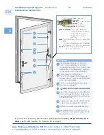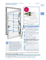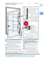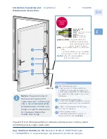
Notice:
The positioning of
frame power supply and
cable transition on the hinge
side is recommended, either
between lower / middle door
hinge or in each case approx.
10 cm above / below the
middle door hinge.
3
EN
Aug. Winkhaus GmbH & Co. KG
∙ Berkeser Straße 6 ∙ 98617 Meiningen
T +49 369 3950 - 0 ∙ www.winkhaus.de ∙ Subject to technical changes
blueMotion
5044745
71
Installation, Operating and
Maintenance Instructions
1
4
2
3
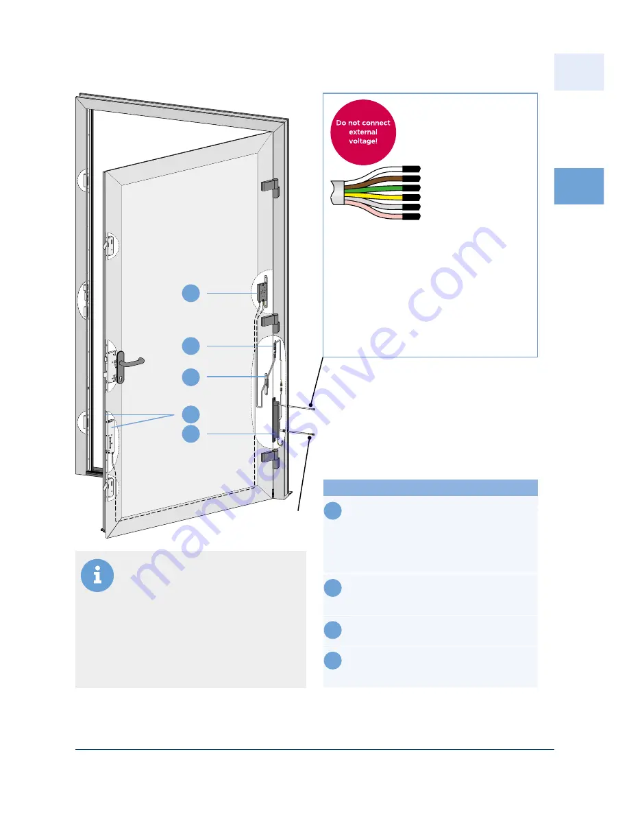
1
white + 24 V DC
brown 0 V
green
yellow
grey
battery pack
pink
(not assigned)
230 V AC
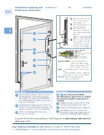
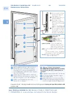
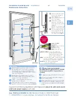
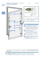
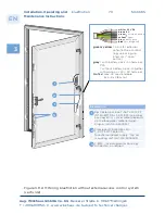
Figure 3.8.2-12: Wiring blueMotion without external access control system
with frame power supply (sash side)
Description
1
Set of cable transition
T-SET KÜ-T1 FT INTEG-BM 3,5 +
1,5 M EST including housing EV-G +
cover plate (depends on the facepla-
te / material type), plug-in (Art.-No.
5040512)
2
Cable transition frame part
T-KÜ-T1 RT KABEL 0,6M RNT, for fra-
me power supply (Art.-No. 5040504)
3
T-BM ... including motor housing,
Art.-No. on request
4
Frame power supply
T-NETZTEILRAHM. 24 V DC 1 A
(2 A/2 S) (Art.-No. 5038589)
}
external opening
signal
green / yellow
= input for external
potential-free contact
(e.g. unlocking via inter-
com / "open" button)
grey
= with battery pack - on terminal
PFS
= without battery pack - together
with white on + 24 V DC terminal
Notice!
max. 40 m extendable
(min. 5 x 0,8 mm
2
)


