3
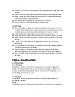
further adjust the angle of the product using the two adjustment knobs located
on the side of the fixture.
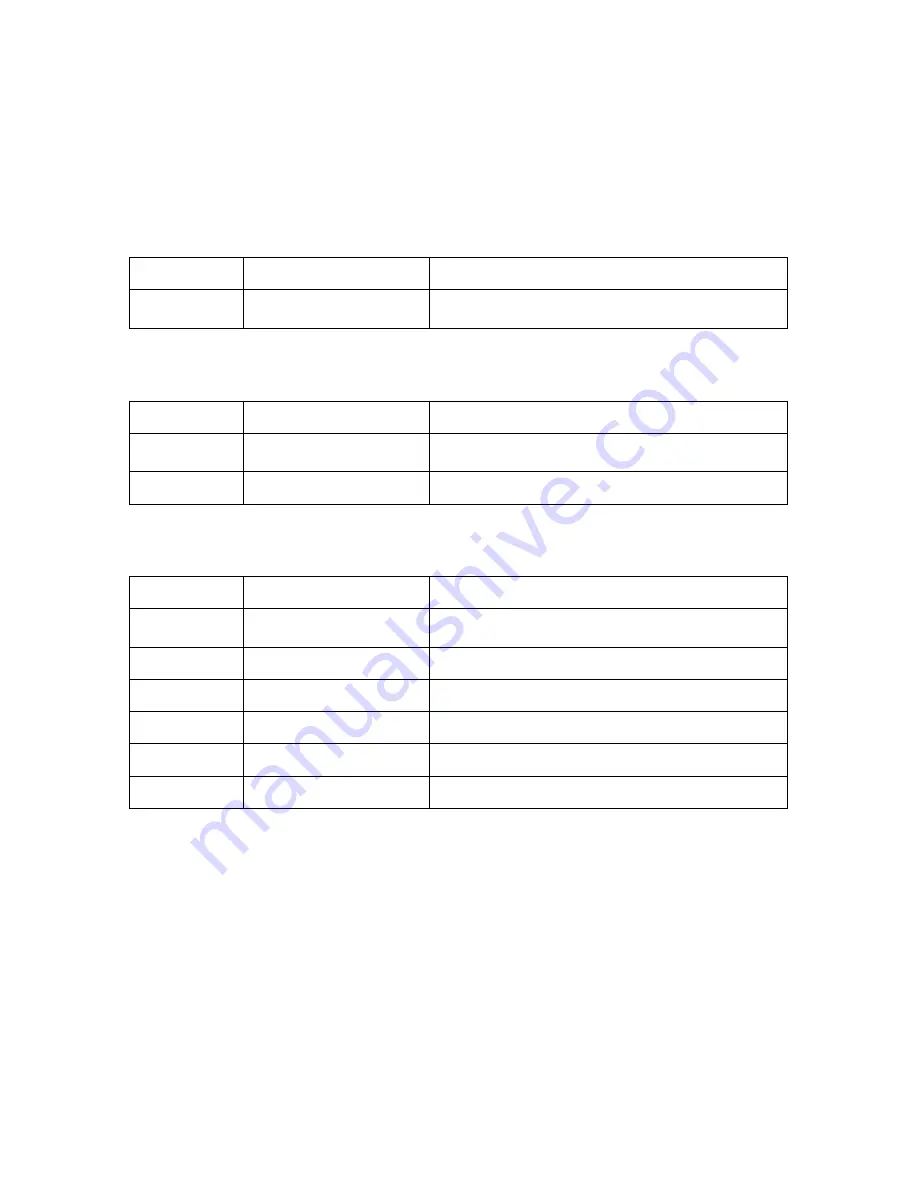
2.2 DMX Channel instruction
1 Channel Mode
Channel
Function
Instruction
CH1
WW Dimmer
WW Dimmer- Dark to Bright
2 Channels Mode
Channel
Function
Instruction
CH1
WW Dimmer
WW Dimmer- Dark to Bright
CH2
CW Dimmer
CW Dimmer- Dark to Bright
6 Channels Mode
Channel
Function
Instruction
CH1
Total Dimmer
Total Dimmer- Dark to Bright
CH2
Total Strobe
Total Strobe- Slow to Fast
CH3
Built-in programs
Built-in programs
CH4
Function/Speed
Speed from slow to Fast
CH5
WW Dimmer
WW Dimmer- Dark to Bright
CH6
CW Dimmer
CW Dimmer- Dark to Bright
2.3 Special construction for DMX connection
☆
At last fixture, the DMX cable has to be terminated with a terminator to
reduce signal errors. Solder a 120-ohm 1/4W resistor between pin
2(DMX-) and pin 3(DMX+) into a 3-pin XLR-plug and plug it in the
DMX-output of the last fixture.
☆
If the controller is 5-pin output, it’s necessary to use an adaptor to transfer
signal from 5-pin output to 3-pin XLR-plug or you can connect cables as
following:


