19
Chapter 2: Installation
2.5 Connector Description
The panel control port is designed for monitors that work with a variety of compatible video
sources. Due to the possible deviations between these signal sources, you may have to make
adjustments to the monitor settings from the OSD menu when switching between these sources.
2.5.1 PoE Connector
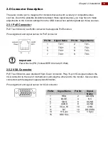
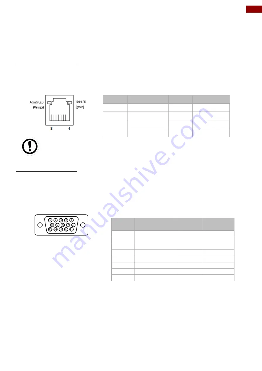
PoE Touch Monitor has RJ45 connector that supports PoE function.
Pin assignment and signal names for PoE connector
Important:
Power Device (PD): follows IEEE 802.3at (25 Watt)
2.5.2 VGA Connector
PoE Touch Monitor uses standard 15pin D-sub connector. Plug 15-pin VGA signal cable to the
VGA connector in the rear of motherboard, and plug the other end to the monitor. Secure cable
connectors with hexagonal copper pillars M3x4mm.
Pin assignment and signal names for VGA connector
Pin №
Signal Name
Pin № Signal Name
1
TX1+
2
TX1-
3
TX2+
4
TX2-
5
TX3+
6
TX3-
7
TX4+
8
TX4-
Pin №
Signal Name
Pin №
Signal
Name
1
RED
2
GREEN
3
BLUE
4
NC
5
GND
6
AGND
7
AGND
8
AGND
9
VGA_5V
10
GND
11
NC
12
DDCSDA
13
H Sync
14
V Sync
15
DDCSCL


