16
17/19/20/24” Military Rack Mount Panel PC User Manual
2.2 Mounting the Device
The Military Panel PC supports different mounting options. Refer to sub-sections below for more
details.
2.2.1 Panel Mount
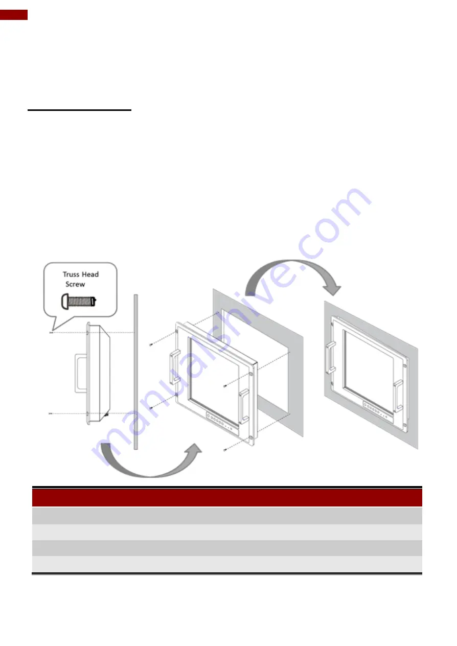
The main mounting approach for military applications is panel mount - very user-friendly in terms
of installation.
Installation Instruction:
1. Prepare a fixture for the specific dimensions of the device.
2. Cut a hole on a sub frame or panel according to the cutout dimensions.
3. Install the device properly onto the cutout area of the sub frame or panel with the sides of the
front bezel.
4. Fix the device from the outside to the fixture with four M6 truss head screws.
Console / Rack Mount Installation
Size
Cutout Dimensions (W x D)
Screw Size
17”
449 x 336 mm
M6 truss head (4 pcs)
19”
449 x 380 mm
M6 truss head (4 pcs)
20.1”
449 x 380 mm
M6 truss head (4 pcs)
24”
563 x 387.3 mm
M6 truss head (4 pcs)
Summary of Contents for R17IK3S-RKA1ML
Page 31: ...31 Chapter 3 BIOS Setup 3 2 2 4 Hardware Monitor...
Page 33: ...33 Chapter 3 BIOS Setup 3 2 2 6 PCI Express Configuration...
Page 35: ...35 Chapter 3 BIOS Setup 3 2 2 9 ME Firmware Configuration...
Page 36: ...36 17 19 20 24 Military Rack Mount Panel PC User Manual...
Page 47: ...47 Chapter 3 BIOS Setup 3 2 6 Exit...
Page 53: ...53 Chapter 4 Driver Installation 3 Select Accept to agree with the terms of license agreement...


