background image


43 

Chapter 3: BIOS Setup 

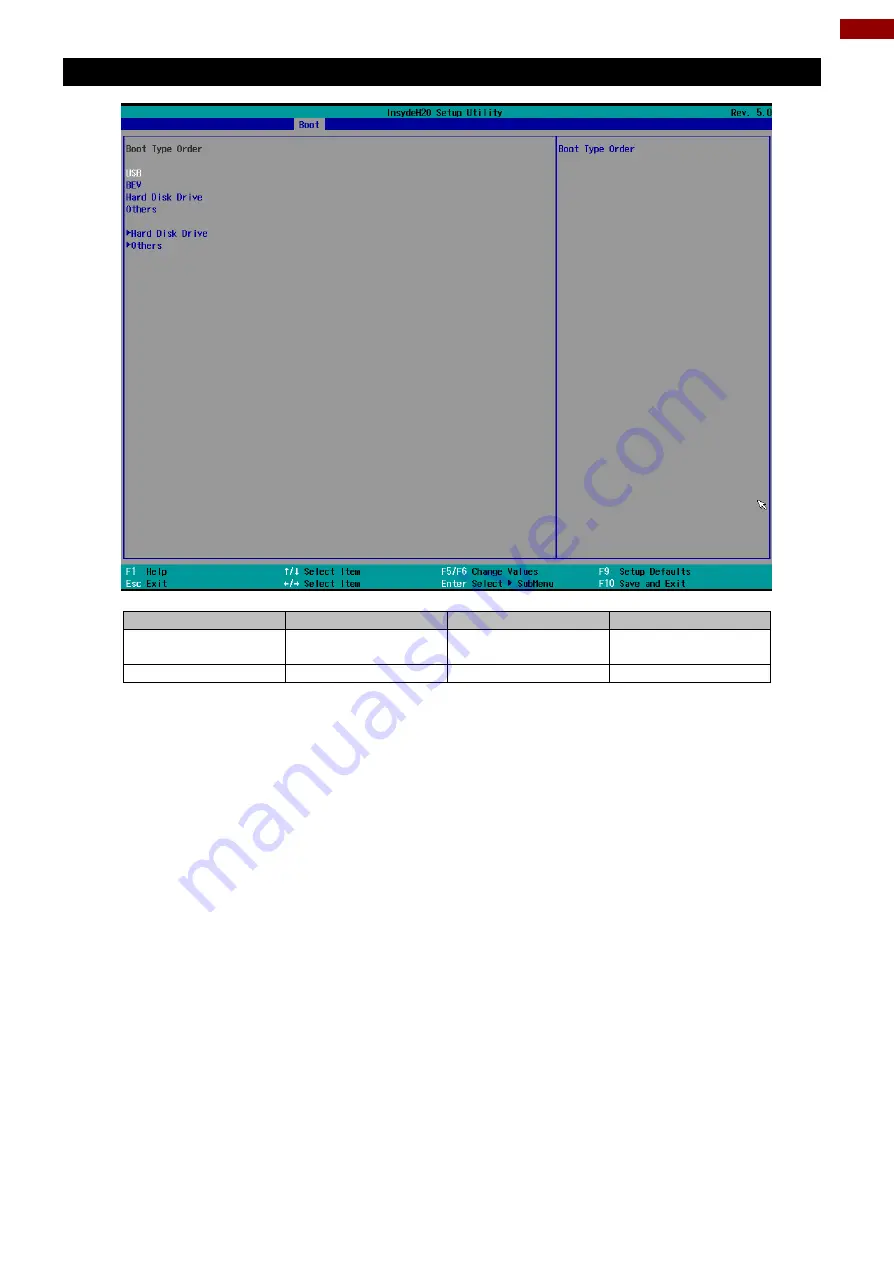
3.2.3.1 Boot Type Order 


BIOS Setting 

Description 

Setting Option 

Effect 

Hard Disk Type 

Hard Disk Type 
configuration 

Enter  

Opens Sub-menu 

Others 

Other configuration 

Enter  

Opens Sub-menu 

Summary of Contents for R17IK3S-RKA1ML

Page 1: ...he device and retain them for future reference 17 19 20 24 Rack Mount Military Panel PC Intel Core i5 7200U Kaby Lake 2 5 GHz Model No R17IK3S RKA1ML R19IK3S RKA3ML R20IK3S RKA2ML W24IK3S RKA2ML User...

Page 2: ...Mount 16 2 2 2 VESA Mount 17 2 3 Powering On 18 2 3 1 Connecting to AC Input Power Source Default 18 2 3 2 Connecting to DC Input Power Source Optional 19 2 4 Connecting Other Devices 20 2 4 1 RS 232...

Page 3: ...56 4 4 Audio Driver 58 4 5 Ethernet Driver 60 4 6 Watchdog Driver Installation 63 Chapter 5 Technical Support 67 5 1 Software Developer Support 68 5 2 Problem Report Form 68 Appendix 69 Appendix A Tec...

Page 4: ...from the invoice date If the customer discovers a defect we will at his her option repair or replace the defective product at no charge to the customer provide it is returned during the warranty perio...

Page 5: ...frequency energy and if not installed and used in accordance with the instruction manual may cause harmful interference to radio communications Operation of this equipment in a residential area is lik...

Page 6: ...s potential damage to hardware and explains how to avoid the potential problem Unealerted attention indique un dommage possible l quipement et explique comment viter le problem potentiel Warning Avert...

Page 7: ...structions The monitor should be operated with an USB cable with Mini USB B type connector on monitor end and standard USB A type connector on the other end to PC or USB signal source Normally it is p...

Page 8: ...Chapter 1 Introduction This chapter gives you product overview describes features and hardware specification You will find all accessories that come with the display device in the packing list Mechan...

Page 9: ...uting platform enables faster searches and real time positioning information providing rapid response capabilities that are incomparable to a standard PC 1 2 Product Features Rack Mount Panel PC featu...

Page 10: ...ata RS 232 422 485 Default setting RS 232 USB 2 0 USB 3 0 connectors Use USB 2 0 or USB 3 0 connector to connect your device to other USB 2 0 USB 3 0 compatible devices HDMI connector Transmits uncomp...

Page 11: ...he brightness of the display screen or allows user to navigate items of a single OSD menu Night Tap this button to enter NIGHT MODE to increase visibility in low light conditions Day Tap this button t...

Page 12: ...19 20 24 Military Rack Mount Panel PC User Manual 1 7 Dimensions 17 inch Panel PC R17IK3S RKA1ML Unit mm Dimensions 482 x 354 x 80 19 inch Panel PC R19IK3S RKA3ML Unit mm Dimensions 482 6 x 374 99 x...

Page 13: ...13 Chapter 1 Introduction 20 1 inch Panel PC R20IK3S RKA2ML Unit mm Dimensions 482 6 x 374 99 x 75 24 inch Panel PC W24IK3S RKA2ML Unit mm Dimensions 609 5 x 382 3 x 79 2...

Page 14: ...Rack Mount Panel PC User Manual Chapter 2 Installation This chapter provides hardware installation instructions and mounting guide for all available mounting options Pay attention to cautions and warn...

Page 15: ...ristics i e different interfaces should be routed separately Be sure to disconnect the power cord before installing and or wiring your device Verify the maximum possible current for each wire gauge es...

Page 16: ...repare a fixture for the specific dimensions of the device 2 Cut a hole on a sub frame or panel according to the cutout dimensions 3 Install the device properly onto the cutout area of the sub frame o...

Page 17: ...the fixture ex swing arm with four M4 VESA screws 3 Place the device on VESA bracket 4 Follow instructions supplied with your mounting kit 5 Connect cables power on the panel PC VESA Mount Installati...

Page 18: ...ppearance by region and country ALTERNATING CURRENT MISE LE TERRE This product must be grounded Use only a grounded AC outlet Install the additional PE ground wire if the local installation regulation...

Page 19: ...y to the DC IN Jack 3 Connect the other end of the DC power cable wires with lug terminals that are labeled and to the terminals of the 9 36V DC Power Source Ensure that the power connections maintain...

Page 20: ...r is off when connecting and disconnecting the connectors Assurez vous que l alimentation est coup e lors de la connexion et la d connexion des connecteurs 2 4 1 RS 232 422 485 Connector The panel PC...

Page 21: ...r Pin Assignment and Signal Names of HDMI Connector 2 4 3 LAN1 LAN2 Gigabit Ethernet Pin RS232 1 DCD 2 RXD 3 TXD 4 DTR 5 GND 6 DSR 7 RTS 8 CTS 9 RI Pin Signal Name Pin Signal Name 1 HDMI_RX2 2 GND 3 H...

Page 22: ...S setup The Power Switch is located on the front side OSD panel You can Turn OFF the device with the Windows power settings To shut down the device 1 Tap Start Shut down 2 Wait for your device to comp...

Page 23: ...n icons 2 Click icon to open Watchdog utility 3 In Watchdog utility window set countdown time and periodically feed time or disable watchdog Example Every 10 min watchdog will monitor the system in ca...

Page 24: ...n on the computer and when the boot screen shows up press Tab F6 to initiate the Recovery Wizard 3 The following screen shows the Recovery Wizard Click Recovery button to continue 4 A warning message...

Page 25: ...25 Chapter 3 BIOS Setup Chapter 3 BIOS Setup This chapter describes the different settings available in the INSYDE BIOS that comes with the board...

Page 26: ...fault settings 3 Modifying the specific hardware specifications 4 Necessity to optimize specifications BIOS Navigation Keys The following keys are enabled during POST Key Function Del Enters the BIOS...

Page 27: ...n processor RC version system language time and date BIOS Setting Description Setting Option Effect Language Displays the system language English is set up by default Adjustment of the language Set th...

Page 28: ...ing pages Caution Handle advanced BIOS settings page with caution Any changes can affect the operation of your computer BIOS Setting Description Setting Option Effect CPU Configuration Configures Trus...

Page 29: ...pabilities provided by Vanderpool Technology Active Processor Cores Number of core to enable in each processor package AII 1 2 3 Select number of core to enable in each processor package Hyper Threadi...

Page 30: ...30 17 19 20 24 Military Rack Mount Panel PC User Manual 3 2 2 2 F81886A Configuration BMP 3 2 2 3 GPIO Configuration...

Page 31: ...31 Chapter 3 BIOS Setup 3 2 2 4 Hardware Monitor...

Page 32: ...I Express clock gating enable disable for each root port Enter Opens sub menu SATA And RST Configuratuion Enable Disable SATA device Enter Opens sub menu USB Configuration Selectively enable disable t...

Page 33: ...33 Chapter 3 BIOS Setup 3 2 2 6 PCI Express Configuration...

Page 34: ...34 17 19 20 24 Military Rack Mount Panel PC User Manual 3 2 2 7 SATA and RST Configuration 3 2 2 8 USB Configuration...

Page 35: ...35 Chapter 3 BIOS Setup 3 2 2 9 ME Firmware Configuration...

Page 36: ...36 17 19 20 24 Military Rack Mount Panel PC User Manual...

Page 37: ...37 Chapter 3 BIOS Setup 3 2 2 10 Power Performance BIOS Setting Description Setting Option Effect CPU Power Management Control Configure CPU Power Management parameters Enter Opens sub menu...

Page 38: ...rs Enabled Disabled Enable Disable Intel Speed Shift Technology support Enabling will expose the CPP v2 interface to allow for hardware controlled P states Turbo Mode Enable or disable Turbo Mode Enab...

Page 39: ...ent SA Configuration BIOS Setting Description Setting Option Effect Graphics Configuration Configure Graphics Configuration parameters Enter Opens sub menu Vt d Intel Virtualization Technology for Dir...

Page 40: ...rture size Note Above 4MB MMIO BIOS assignment is automatically enabled when selecting 2048MB aperture To use this feature please disable CSM port DVMT Pre Allocated Select DVMT Pre Allocated 0M 60M S...

Page 41: ...41 Chapter 3 BIOS Setup Vt d BIOS Setting Description Setting Option Effect Vt d Intel Virtualization Technology for Directed I O Enabled Disabled Vt d capability...

Page 42: ...ws InsydeH20 to skip certain tests while booting This will decrease the time needed to boot the system Quiet Boot Quiet Boot configuration Enabled Disabled Disable or enable booting in text Mode Timeo...

Page 43: ...hapter 3 BIOS Setup 3 2 3 1 Boot Type Order BIOS Setting Description Setting Option Effect Hard Disk Type Hard Disk Type configuration Enter Opens Sub menu Others Other configuration Enter Opens Sub m...

Page 44: ...44 17 19 20 24 Military Rack Mount Panel PC User Manual 3 2 3 1 1 Hard Disk Type 3 2 3 1 2 Others...

Page 45: ...PM Availability configuration Available Hidden When hidden don t exposes TPM to 0 TPM Operation TPM Operation configuration Select one of the supported operation to change TPM2state Clear TPM Clear TP...

Page 46: ...S Setting Description Setting Option Effect ACPI S3 ACPI S3 configuration Disabled Enabled Enable Disable ACPI S1 S3 Sleep state Auto Wake on S5 Auto Wake on S5 configuration Disabled By Every Day By...

Page 47: ...47 Chapter 3 BIOS Setup 3 2 6 Exit...

Page 48: ...48 17 19 20 24 Military Rack Mount Panel PC User Manual Chapter 4 Driver Installation This chapter provides guideline to driver installation...

Page 49: ...49 Chapter 4 Driver Installation 4 1 Chipset Driver Follow instructions below to install Chipset driver 1 Open the Driver CD included in the package and select Chipset driver...

Page 50: ...50 17 19 20 24 Military Rack Mount Panel PC User Manual 2 Installation window will pop up select Next 3 Select Accept to agree with the terms of license agreement...

Page 51: ...Chapter 4 Driver Installation 4 Check the ReadMe file information select Install to continue 5 Wait for the driver to be installed When installation completed select Restart Now to restart your comput...

Page 52: ...y Rack Mount Panel PC User Manual 4 2 Graphic Driver Follow instructions below to install Graphic driver 1 Open the Driver CD included in the package and select Graphic driver 2 Installation window wi...

Page 53: ...53 Chapter 4 Driver Installation 3 Select Accept to agree with the terms of license agreement...

Page 54: ...54 17 19 20 24 Military Rack Mount Panel PC User Manual 4 Check the ReadMe file information select Next to continue 5 Wait for the driver to be installed...

Page 55: ...55 Chapter 4 Driver Installation 6 Select Next to continue 7 After installation is completed select Yes I want to restart this computer now and click Finish...

Page 56: ...y Rack Mount Panel PC User Manual 4 3 Management Engine ME Follow instructions below to install Management Engine ME 1 Open the Driver CD included in the package and select ME driver 2 Select Next to...

Page 57: ...57 Chapter 4 Driver Installation 3 Select Next to agree with the terms of license agreement 4 Wait for the driver to be installed...

Page 58: ...Mount Panel PC User Manual 5 When installation completed select Finish complete installation 4 4 Audio Driver Follow instructions below to install Audio driver 1 Open the Driver CD included in the pac...

Page 59: ...59 Chapter 4 Driver Installation 2 Select Next to continue 3 When installation completed select Finish complete installation...

Page 60: ...litary Rack Mount Panel PC User Manual 4 5 Ethernet Driver Follow instructions below to install LAN driver 1 Open the Driver CD included in the package and select LAN driver 2 When compression is comp...

Page 61: ...61 Chapter 4 Driver Installation 3 Read the license agreement and then select Next 4 System displays the installed packages select Next...

Page 62: ...62 17 19 20 24 Military Rack Mount Panel PC User Manual 5 Confirm the installation select Install to start the installation 6 When installation is completed select Finish to close the window...

Page 63: ...2017 Embedded 20Computing Watchdog 20Guide_ IB_IH_IV_IK pdf Follow instructions below to install Watchdog driver 1 Type cmd in the run box then the cmd exe will appear in programs 2 Right click on the...

Page 64: ...19 20 24 Military Rack Mount Panel PC User Manual 5 Wait for installation to complete When installation is complete press any key to close 6 Open the Driver CD included in the package and select Watch...

Page 65: ...65 Chapter 4 Driver Installation 7 Select Next 8 The installed storage location is displayed select Next to continue...

Page 66: ...66 17 19 20 24 Military Rack Mount Panel PC User Manual 9 Select Install to start the installation 10 When installation is completed select Finish to close the window...

Page 67: ...upport Free technical support is available from our engineers every business day We are always ready to give advice on application requirements or specific information on the installation and operatio...

Page 68: ...the problem as soon as possible ______________________________________________________________________________ ______________________________________________________________________________ _________...

Page 69: ...69 Appendix Appendix This chapter contains additional product information including troubleshooting guide and frequency table...

Page 70: ...J 45 2 x RJ 45 COM 1 x RS232 422 485 Default RS232 1 x RS232 Optional 1 x RS232 422 485 Default RS232 1 x RS232 Optional 1 x RS232 422 485 Default RS232 1 x RS232 Optional 1 x RS232 422 485 Default RS...

Page 71: ...S 116 CS101 CS 106 CS 109 CS 114 CS 115 CS 116 CS101 CS 106 CS 109 CS 114 CS 115 CS 116 MIL STD 810F G Compliance Vibration MIL STD 810F G Method 514 5 MIL STD 810F G Method 514 5 MIL STD 810F G Metho...

Page 72: ...90 dB CE102 Conducted Emissions 30Hz 10kHz 10kHz 500KHz 100 66dB 500KHz 10MHz 66dB RE101 Radiated Emissions 30Hz 100kHz 30 100k 180 110 dBpT RE102 Radiated Emissions 10kHz 18GHz 2MHz 18G Hz 44 89 dB M...

Page 73: ...aining or discoloration may occur Cleaning the Casing Use the following procedure to clean the equipment Caution Attention Always turn off the device and disconnect other peripherals before cleaning a...

Page 74: ...4 17 19 20 24 Military Rack Mount Panel PC User Manual Appendix D Serial Port Settings To change serial port settings enter the BIOS setup menu by pressing DEL key during POST Go to Advanced SIOF81866...

Page 75: ..._______________________________________________________________ ______________________________________________________________________________ _________________________________________________________...

Page 76: ...Winmate Inc 9F No 111 6 Shing De Rd San Chung District New Taipei City 24158 Taiwan R O C www winmate com Copyright Winmate Inc All rights reserved...

Reviews: