background image

ball bearing retainer

14

13

Chart 6

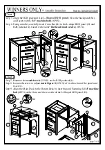
Step 13. Insert the two Grommets on top of the Main Desk.
Step 14. 

Install the Center Drawer (L) in place.

Important:

(Be sure to move the ball bearing retainer all the way to the front of the glide
and carefully slide the rails into the glides and ball bearing retainer.)

Assembly is now complete

Chart 5

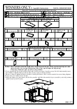
Step 10. Connect 

LHS Glide Panel

 (D) and 

RHS Glide Panel 

(E) to 

R1 Desk top 

(B) by slightly

              tightening 

1-1/4" Machine Bolt 

(6PCS) install the

 Keyboard Pullout

 (C) in place, fasten

              the previously installed 

1-1/4" machine Bolts

 (6PCS), insert 

1-1/4" Flat Head Wood

              Screws

 (6PCS) to reinforce the assembly.

Step 11.

Connect 

L-Shaped LHS panel

 (H)

 to 

R1 Desk Top

 (B) and use 

1-1/4" machine bolts 

(3PCS)

             and 

1-1/4" flat head wood screw

 (2PCS) to reinforce the assembly.

Step 12. Insert 

short (3/4") flat head wood screws

 (14 PCS) through metal figure 8 to connect  

R1


Desk Top 

(B) to Main Desk base and 

R2 Desk Top

  (I) to Return Desk base.

X6

B

12

X14

I

12

10

10

X6

E

D

12

L

11

X3

X2

11

11

H

D

E

D

E

B

B

ball bearing retainer

10

C

Summary of Contents for GDB166LWR

Page 1: ...aple tips can cause injury therefore for your protection please remove any exposed staples used in packing Please keep all hardware parts out of the reach of children 1 We recommend that you should assemble this product with the assistance of another person this will make assembly easier and will help to eliminate damage to the product or injury to persons during assembly 2 Be sure to check all pa...

Page 2: ...by slightly tightening 1 1 4 Machine Bolt 6PCS install the Keyboard Pullout C in place fasten the previously installed 1 1 4 machine Bolts 6PCS insert 1 1 4 Flat Head Wood Screws 6PCS to reinforce the assembly Step 11 Connect L Shaped LHS panel H to R1 Desk Top B and use 1 1 4 machine bolts 3PCS and 1 1 4 flat head wood screw 2PCS to reinforce the assembly Step 12 Insert short 3 4 flat head wood s...

Page 3: ...the Return Desk by inserting and Fastening 1 1 4 machine bolt 4PCS at the front and the rear side of the L Shaped LHS panel H Chart 3 Step 5 Align the R2B pedestal J L Shaped RHS panel N to the back panel M and fasten with 1 1 4 machine bolts 6PCS Step 6 Using a mallet carefully insert Cross Bar K to the L shape RHS panel N and R2B pedestal J fasten with 1 1 4 flat head wood screws 2 PCS X6 X2 ...

Page 4: ...with 1 1 4 machine bolts 6PCS Chart 2 Step 2 Align the R1B pedestal A LSF RSF side panel G1 G2 to the back panel F and fasten with 1 1 4 machine bolts 6PCS Step 3 Hammer the wood dowels 5 PCS on the R1B pedestal A LSF RSF side panel G1 G2 Step 4 Loosen the screw to adjust metal figure 8 8 PCS of its direction of the panel and re screw X8 X5 2 2 2 ...

Reviews: