5
5
5
5
6
6
6
3
4
3
2
X4
X4
X12
X1
Chart 3
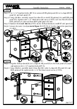
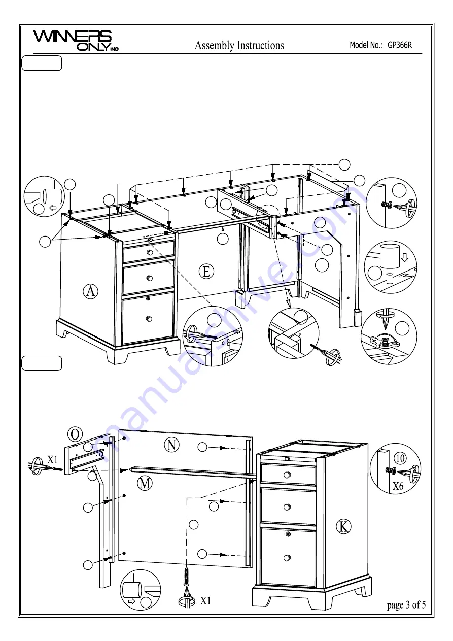
Step 3. Use 1-1/4" machine bolts (4PCS) to connect RHS glide panel (D) to L-shaped RHS
panel (I) and back panel (E).
Step 4. Using a Mallet, carefully insert Cross Bar (H) to the R1B pedestal (A) and RHS glide
panel (D), tighten with 1-1/4" flat head wood screws (2 PCS) to Cross Bar (H) from
R1B pedestal (A) side and from RHS glide panel (D) side.
Step 5. Hammer the
wood dowels
(4 PCS) on the R1B pedestal (A) and RSF side panel (G).
Step 6. Loosen the screw to adjust
metal figure 8
(12 PCS) of its direction of the panel and
re-screw.
H
D
I
G
4
X1
3
Remove strap
4
10
11
11
Chart 4
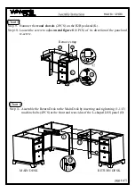
Step 7. Align the R2B pedestal (K) & L-shaped LHS panel (O) to the back panel (N),insert
and tighten with 1-1/4" machine bolts (6PCS).
Step 8. Using a Mallet, carefully insert Cross Bar (M) to the L-shaped LHS panel (O) and
R2B pedestal (K), tighten with 1-1/4" flat
head wood screws
(2 PCS).
10
10
10
11
10
10

