background image

56 

W

INNOV 

C

BOX 

H

ARDWARE 

U

SER 

G

UIDE


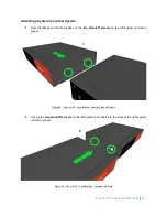
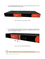
3. 

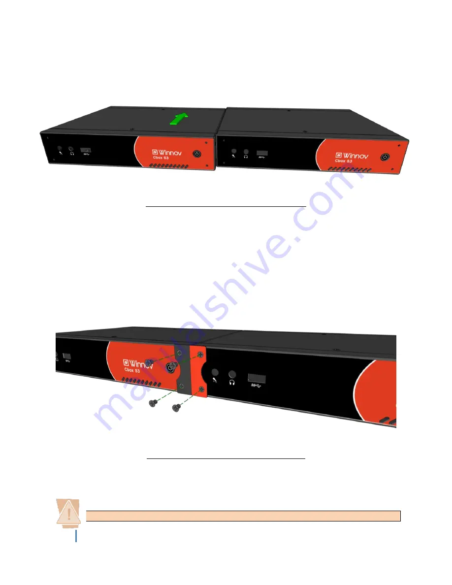
Once the 

standoff screws

 are inserted into the slots, slide the left system toward the rear of the 

right system, locking the two systems together. 


Figure 70 - Cbox L3/S3 – Lock Bracket - Attach Two Systems


4. 

Align the 

lock bracket holes

 to right side of the left system and the left side of the right system 

as  pictured  below.  Using  a 

2.5mm  allen  or  hex  key

,  screw 

(4)  6mm  hex  screws

  to securely 

attach the 

lock bracket

 to the systems. 


Figure 71 - Cbox L3/S3 – Attaching Lock Bracket to Systems


Please note that the allen or hex key is 

not

 included with the Cbox rack mount kit 


Summary of Contents for CBOX

Page 1: ...CBOX HARDWARE USER GUIDE Version 2 0 4 Updated 4 26 2016 ...

Page 2: ...2 WINNOV CBOX HARDWARE USER GUIDE ...

Page 3: ...Date Section s Page s Summary of Changes 2 0 0 8 4 2015 Initial Version 2 0 1 11 15 2015 8 17 26 35 Revision to Audio Inputs 2 0 2 3 9 2016 7 Added 2 DVI to HDMI adapters 2 0 3 4 18 2016 27 34 Added Cbox S3 Plus section 2 0 4 4 26 2016 11 13 Enhanced Technical AV specifications ...

Page 4: ...FETY INSTRUCTIONS 14 SYSTEM POWER 14 ELECTROSTATIC DISCHARGE ESD AND ESD PROTECTION 14 SAFETY NOTICE AND WARNINGS 14 FCC NOTICE 14 CE MARK WARNING 15 ENVIRONMENTAL WARNING 15 INSTALLATION SAFETY NOTES 15 GETTING STARTED WITH THE APPLIANCE 16 2 CBOX P3 17 RECORD OF CBOX P3 HARDWARE REVISIONS 18 RIGHT PANEL 18 LEFT PANEL 19 TOUCHSCREEN MONITOR 19 POWERING ON THE SYSTEM 20 AUDIO VIDEO INPUTS AND OUTP...

Page 5: ...E VERSION 36 BACK PANEL PUSH PIN VERSION 36 AUDIO VIDEO INPUTS AND OUTPUTS BREAKOUT CABLE VERSION 37 AUDIO OUT FOR ROOM SOUND SYSTEM BREAKOUT CABLE VERSION 37 AUDIO VIDEO INPUTS AND OUTPUTS PUSH PIN VERSION 38 AUDIO OUT FOR ROOM SOUND SYSTEM PUSH PIN VERSION 38 DVI HDMI RGB INPUTS 39 SD HD 3G SDI INPUTS 39 MINI DISPLAYPORT VIDEO OUTPUTS 40 AUDIO MONITOR OUTPUT 40 MOUSE AND KEYBOARD 40 GENERAL PURP...

Page 6: ...PUTS AND OUTPUTS 50 USING A PANASONIC PTZ CAMERA 50 APPENDIX 51 CBOX L3 S3 RACK MOUNT INSTRUCTIONS SINGLE SYSTEM 52 CBOX L3 S3 RACK MOUNT INSTRUCTIONS SYSTEM SYSTEM 54 CBOX S3 PLUS RACK MOUNT INSTRUCTIONS SINGLE SYSTEM 59 CBOX S3 PLUS RACK MOUNT INSTRUCTIONS SYSTEM SYSTEM 61 ...

Page 7: ...ut prior written permission from Winnov This appliance is protected by copyright law and international treaties Unauthorized reproduction or distribution of this program or any portion of it may result in severe civil and criminal penalties and will be prosecuted to the maximum extent possible under the law Copyright 2016 by Winnov LP All rights reserved DISCLAIMER Winnov shall not be liable for a...

Page 8: ...Cbox L3 Pushpin Cbox L3 Breakout Cable Appliance and AC Power Cord 19V Power Adapter with Multi country Plugs USB Mouse and Keyboard A V Breakout Cable DMS 59 Adapter Cable 2 DVI to HDMI Adapter Mini DisplayPort to HDMI Adapter Cable MS Windows 8 1 Software License Rack Mount Kit one system Optional Optional Optional Optional Optional Optional Rack Mount Kit two systems Optional Optional Optional ...

Page 9: ...alanced mono Mic Line via XLR 1 Stereo balanced via XLR 4 Stereo unbalanced via RCA connectors 6 SDI embedded audio channels 2 HDMI embedded audio channels All 5 Analog Embedded 2 Stereo balanced 3 Stereo unbalanced via 1 8 TRS jacks 6 SDI embedded audio channels 2 HDMI embedded audio channels Any 7 Analog Embedded 2 balanced mono Mic Line via XLR 1 Stereo balanced via XLR 4 Stereo unbalanced via ...

Page 10: ...cks 6 SDI embedded audio channels 2 HDMI embedded audio channels Any 2 upgradeable to 3 Analog Embedded 2 balanced mono Mic Line via XLR 1 Stereo balanced via XLR 4 Stereo unbalanced via RCA connectors 6 SDI embedded audio channels 2 HDMI embedded audio channels Audio Output 1 Stereo balanced via terminal block 1 Headphone 1 Headset 1 Stereo balanced via XLR 1 Headphone 1 Headset Connectivity 3 US...

Page 11: ...emale 5 7 dBu 7 8 dBV 2 5 dB to 49 5 dB Selectable 48V or Off 2K Ohms Mono signal replicated on L R channels Audio IN 2 Audio IN 3L Stereo Balanced XLR Female 5 7 dBu 7 8 dBV 2 5 dB to 49 5 dB Selectable 48V or Off 2K Ohms Stereo signal Left Channel Audio IN 3R Stereo signal Right Channel Audio 4 Stereo Unbalanced RCA 4 9 dBu 2 7 dBV 25 dB to 12 dB No 10K Ohms Stereo Audio 5 Audio 6 Audio 7 Audio ...

Page 12: ... Selectable 48V or Off 2K Ohms Stereo signal Left Channel Audio IN 1R Stereo signal Right Channel Audio IN 2L Stereo Balanced Push In Spring Connection 5 7 dBu 7 8 dBV 2 5 dB to 49 5 dB Selectable 48V or Off 2K Ohms Stereo signal Left Channel Audio IN 2R Stereo signal Right Channel Audio 3 Stereo Unbalanced 1 8 TRS 4 9 dBu 2 7 dBV 25 dB to 12 dB No 10K Ohms Stereo Audio 4 Audio 5 Audio Out L Stere...

Page 13: ...C SD SMPTE 259 HD SMPTE 292 3G SMPTE 494 Level A Level B Up to 1080p60 NTSC and PAL Interlaced and Progressive SMPTE 292 2 x Stereo 48 Khz Additional channel pairs are optional SDI IN 2 SDI IN 3 Analog Video IN Composite Analog CVBS BNC NTSC 480i60 PAL 576i50 Figure 5 Technical Video Specifications Breakout Cable and Push Pin version Cbox does not capture from HDCP encrypted sources NOTE The base ...

Page 14: ...mponents Before connecting or disconnecting any device to the Winnov Cbox appliance we recommend you discharge static electricity by first touching a metal part of a grounded PC CAUTION To reduce the risk of electric shock do not open chassis do not defeat or remove the ground pin of the power cord connect only to a properly grounded ac power outlet No user serviceable parts inside Refer servicing...

Page 15: ...ions Title 22 Division 4 5 Chapter 33 Best Management Practices for Perchlorate Materials This product part includes a battery that contains Perchlorate material INSTALLATION SAFETY NOTES Do not place the Winnov Cbox appliance underneath heavy loads or in an unstable position Do not expose the Winnov Cbox appliance under direct sunlight high humidity or wet conditions Do not use or expose the Winn...

Page 16: ...4 Do not block the equipment vents READ THE FOLLOWING SAFETY INFORMATION THOROUGHLY BEFORE INSTALLING THIS WINNOV PRODUCT FAILURE TO FOLLOW THIS SAFETY INFORMATION MAY LEAD TO PERSONAL INJURY OR DAMAGE TO THE EQUIPMENT Power Supply This unit must be grounded The unit must be connected to a grounded outlet to comply with product safety standards The grounded socket outlet shall be installed near th...

Page 17: ...WINNOV CBOX HARDWARE USER GUIDE 17 2 CBOX P3 ...

Page 18: ...BOX P3 HARDWARE REVISIONS Revision Number Date Section s Page s Summary of Changes 1 0 8 4 2015 Initial Revision 1 1 11 15 2015 17 Revision to Audio Inputs RIGHT PANEL Figure 6 Cbox P3 Right Panel AC Power Connector Power Supply Switch Power Button ...

Page 19: ... Figure 8 Cbox P3 Touchscreen Monitor Integrated Touchscreen Monitor Microphone In Gigabit Ethernet 6 USB 3 0 Ports DVD CD R RW Front Out Line In 3 SD HD 3G SDI Inputs DMS 59 Adapter Cable Connector HDMI Out 2 USB 2 0 Ports A V Breakout Cable Connector 4 General purpose Inputs Outputs PS 2 Port ...

Page 20: ...ERING ON THE SYSTEM To power on the appliance first turn power supply switch to the ON position marked Next press the power button to power on the P3 system Figure 9 Cbox P3 Power Supply Switch Power Button Power Supply Switch Power Button ...

Page 21: ...MS 59 adapter cable and DVI to HDMI adapter Cbox supports connection of an analog composite video source When using the composite input connect the camera to the Video 1 IN input of the A V breakout cable Figure 10 Cbox P3 A V Breakout Cable AUDIO OUT FOR ROOM SOUND SYSTEM The audio output of Cbox appliance can be used to connect to the room sound system or to a PC speaker set The A V breakout cab...

Page 22: ...MI RGB 1 video input and DVI HDMI RGB 2 video input Use the included DVI to HDMI adapters to connect one or two HDMI input s Figure 12 Cbox P3 DMS 59 Adapter Cable SD HD 3G SDI INPUTS The SD HD 3G SDI inputs must be connected to the BNC connectors on the back panel Figure 13 Cbox P3 HD 3G SDI Input s BNC Connector BNC connectors for SD HD 3G SDI inputs DMS 59 adapter cable needs to be connected to...

Page 23: ...ices monitors projectors etc The secondary display can be used to show a video mix controlled via the Cbox Amalga Software Figure 14 Cbox P3 VGA HDMI Display Outputs AUDIO MONITOR OUTPUT If you want to use headphones connect them on the back panel Figure 15 Cbox P3 Headphone Out VGA Display Output HDMI Display Output Front Out Headphone Out ...

Page 24: ...s may be used to activate external triggers E g pressure mats footswitches button panel Triggers may be used to control and manage specific functions such as starting a recording controlling pan tilt zoom cameras and switching input sources NOTE The General Purpose Inputs and Outputs feature will be enabled in a future software update Figure 17 Cbox P3 General purpose Inputs and Outputs PS 2 Port ...

Page 25: ...AMERA Panasonic AW HE2 AW HE40 AW HE50 AW HE120 and AW HE 130 pan tilt zoom cameras can be used with Cbox The PTZ control feature requires configuration to control over IP Please refer to the Cbox Software User Guide Figure 18 Cbox P3 and Panasonic PTZ cameras ...

Page 26: ...26 WINNOV CBOX HARDWARE USER GUIDE 3 CBOX S3 PLUS ...

Page 27: ...WINNOV CBOX HARDWARE USER GUIDE 27 RECORD OF CBOX S3 PLUS HARDWARE REVISIONS Revision Number Date Section s Page s Summary of Changes 1 0 8 4 2015 Initial Revision ...

Page 28: ...ble version 2 USB 3 0 Ports Power Button Headphone Out Microphone In LED Status Indicator Lights Reset Button DMS 59 Adapter Cable Connector AC Power Connector Dual Gigabit Ethernet DVI D Output 3 HD 3G SDI Inputs HDMI Output P PS 2 Port AV Breakout Cable Connector 4 General purpose Inputs Outputs 6 3 0 USB Ports 2 2 0 USB Ports Line In Front Out Microphone In ...

Page 29: ...Mono Mic Line XLR 1 Stereo Balanced XLR 4 stereo unbalanced RCA 6 SDI embedded audio channels BNC connectors 2 HDMI embedded audio channels DMS 59 adapter cable and DVI to HDMI adapter Cbox supports connection of an analog composite video source When using the composite input connect the camera to the Video 1 IN input of the A V breakout cable Figure 22 Cbox S3 Plus Breakout Cable version A V Brea...

Page 30: ...in version The terminal block provides two stereo balanced inputs Audio IN 1 R Audio IN 1 L Audio IN 2 R Audio IN 2 L 1 8 jacks provide three stereo unbalanced inputs Cbox S3 Plus Push Pin version supports connection of the following 2 stereo balanced terminal block 3 stereo unbalanced 1 8 TRS jack 6 SDI embedded audio channels BNC connectors 2 HDMI embedded audio channels DMS 59 adapter cable and...

Page 31: ... connect up to two DVI HDMI RGB inputs simultaneously via the DVI I connectors The DVI I connectors are numbered 1 and 2 and correspond to DVI HDMI RGB 1 video input and DVI HDMI RGB 2 video input Use the included DVI to HDMI adapters to connect one or two HDMI input s Figure 26 Cbox S3 Plus Breakout Cable version DMS 59 Adapter Cable Figure 27 Cbox S3 Plus Push Pin version DMS 59 Adapter Cable Te...

Page 32: ...uts can be used to connect either one or two output devices monitors projectors etc The secondary display can be used to show a video mix controlled via the Cbox Amalga Software Figure 29 Cbox S3 Plus DVI and HDMI Video Outputs AUDIO MONITOR OUTPUT If you want to use headphones connect them on the front panel Figure 30 Cbox S3 Plus Front Panel Headphones Headphone Out DVI D Output HDMI Output 1 2 ...

Page 33: ...ing controlling pan tilt zoom cameras and switching inputs sources The GPIO control feature requires configuration NOTE The General Purpose Inputs and Outputs feature will be enabled in a future software update Figure 32 Cbox S3 Plus General purpose Inputs and Outputs USING A PANASONIC PTZ CAMERA Panasonic AW HE2 AW HE40 AW HE50 AW HE120 and AW HE 130 pan tilt zoom cameras can be used with Cbox Th...

Page 34: ...34 WINNOV CBOX HARDWARE USER GUIDE 4 CBOX S3 ...

Page 35: ...WINNOV CBOX HARDWARE USER GUIDE 35 RECORD OF CBOX S3 HARDWARE REVISIONS Revision Number Date Section s Page s Summary of Changes 1 0 8 4 2015 Initial Revision 1 1 11 15 2015 26 Revision to Audio Inputs ...

Page 36: ...utton Microphone In Headphone Out DC Power Connector DMS 59 Adapter Cable Connector 3 SD HD 3G SDI Inputs A V Breakout cable connector 4 General purpose Inputs Outputs 2 Mini DisplayPort 2 USB 3 0 Ports Gigabit Ethernet 4 General purpose Inputs Outputs DC Power Connector 3 1 8 TRS jack DMS 59 Adapter Cable Connector 3 SD HD 3G SDI Inputs Headphone Out Terminal Block for Audio Inputs Outputs 2 Mini...

Page 37: ...udio channels DMS 59 adapter cable and DVI to HDMI adapter Cbox supports connection of an analog composite video source When using the composite input connect the camera to the Video 1 IN input of the A V breakout cable Figure 37 Cbox S3 Breakout Cable version A V Breakout Cable AUDIO OUT FOR ROOM SOUND SYSTEM BREAKOUT CABLE VERSION The audio output of Cbox S3 can be used to connect to the room so...

Page 38: ...o HDMI adapter Cbox supports connection of an analog composite video source When using the composite input connect the camera to the BNC connector labeled Video 1 IN Figure 39 Cbox S3 Push Pin version Audio Video Inputs AUDIO OUT FOR ROOM SOUND SYSTEM PUSH PIN VERSION The audio output of Cbox S3 can be used to connect to the room sound system or to a PC speaker set It provides a balanced line leve...

Page 39: ...Cbox S3 Push Pin version DMS 59 Adapter Cable SD HD 3G SDI INPUTS The SD HD 3G SDI inputs must be connected to the BNC connectors on the back panel Figure 43 Cbox S3 SD HD 3G SDI Input s NOTE The base configuration Cbox S3 has THREE upgradeable to FIVE HD input channels and one analog composite input enabled However it is possible to enable additional HD input channels upon approval of your accoun...

Page 40: ...o show a video mix controlled via the Cbox Amalga Software Figure 44 Cbox S3 Mini DisplayPort Video Outputs AUDIO MONITOR OUTPUT If you want to use headphones connect them on the front panel Figure 45 Cbox S3 Front Panel Headphones MOUSE AND KEYBOARD Use the USB 3 0 ports when connecting the mouse and the keyboard to the Cbox appliance Figure 46 Cbox S3 USB 3 0 Ports Headphone Out 2 Mini DisplayPo...

Page 41: ...rces The GPIO control feature requires configuration NOTE The General Purpose Inputs and Outputs feature will be enabled in a future software update Figure 47 Cbox S3 General purpose Inputs and Outputs USING A PANASONIC PTZ CAMERA Panasonic AW HE2 AW HE40 AW HE50 AW HE120 and AW HE 130 pan tilt zoom cameras can be used with Cbox The PTZ control feature requires configuration to control over IP Ple...

Page 42: ...42 WINNOV CBOX HARDWARE USER GUIDE ...

Page 43: ...WINNOV CBOX HARDWARE USER GUIDE 43 5 CBOX L3 ...

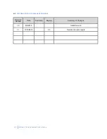
Page 44: ...44 WINNOV CBOX HARDWARE USER GUIDE RECORD OF CBOX L3 HARDWARE REVISIONS Revision Number Date Section s Page s Summary of Changes 1 0 8 4 2015 Initial Revision 1 1 11 15 2015 35 Revision to Audio Inputs ...

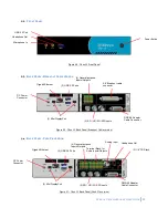
Page 45: ...utton Microphone In Headphone Out DC Power Connector DMS 59 Adapter Cable Connector 3 SD HD 3G SDI Inputs A V Breakout cable connector 4 General purpose Inputs Outputs 2 Mini DisplayPort 2 USB 3 0 Ports Gigabit Ethernet 4 General purpose Inputs Outputs DC Power Connector 3 1 8 TRS jack DMS 59 Adapter Cable Connector 3 SD HD 3G SDI Inputs Headphone Out Terminal Block for Audio Inputs Outputs 2 Mini...

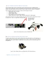
Page 46: ...udio channels DMS 59 adapter cable and DVI to HDMI adapter Cbox supports connection of an analog composite video source When using the composite input connect the camera to the Video 1 IN input of the A V breakout cable Figure 52 Cbox L3 Breakout Cable version A V Breakout Cable AUDIO OUT FOR ROOM SOUND SYSTEM BREAKOUT CABLE VERSION The audio output of Cbox L3 can be used to connect to the room so...

Page 47: ...o HDMI adapter Cbox supports connection of an analog composite video source When using the composite input connect the camera to the BNC connector labeled Video 1 IN Figure 54 Cbox L3 Push Pin version Audio Video Inputs AUDIO OUT FOR ROOM SOUND SYSTEM PUSH PIN VERSION The audio output of Cbox L3 can be used to connect to the room sound system or to a PC speaker set It provides a balanced line leve...

Page 48: ...ush Pin version DMS 59 Adapter Cable SD HD 3G SDI INPUTS The SD HD 3G SDI inputs must be connected to the BNC connectors on the back panel Figure 58 Cbox L3 Push Pin version DMS 59 Adapter Cable NOTE The base configuration Cbox L3 has TWO upgradeable to THREE HD input channels and one analog composite input enabled However it is possible to enable an additional HD input channel upon approval of yo...

Page 49: ...o show a video mix controlled via the Cbox Amalga Software Figure 59 Cbox L3 Mini DisplayPort Video Outputs AUDIO MONITOR OUTPUT If you want to use headphones connect them on the front panel Figure 60 Cbox L3 Front Panel Headphones MOUSE AND KEYBOARD Use the USB 3 0 ports when connecting the mouse and the keyboard to the Cbox appliance Figure 61 Cbox L3 USB 3 0 Ports Headphone Out 2 Mini DisplayPo...

Page 50: ...hing inputs sources The GPIO control feature requires configuration NOTE The General Purpose Inputs and Outputs feature will be enabled in a future software update Figure 62 Cbox L3 General purpose Inputs and Outputs USING A PANASONIC PTZ CAMERA Panasonic AW HE2 AW HE40 AW HE50 AW HE120 and AW HE 130 pan tilt zoom cameras can be used with Cbox The PTZ control feature requires configuration to cont...

Page 51: ...WINNOV CBOX HARDWARE USER GUIDE 51 APPENDIX ...

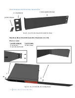
Page 52: ...k Mount Kit with Extended Ear Bracket Cbox Rack Mount Kit with Extended Ear Bracket for L3 or S3 What is included 1 joint kit 2 pieces 1 set of screws 1 ear bracket 1 extended ear bracket 4 6mm screws Figure 65 Cbox L3 S3 Rack Mount Kit Attaching Brackets 2 1 4 6mm screws 1 Ear Bracket 1 Extended Ear Bracket ...

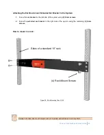
Page 53: ...he left side of the system using 2 6mm screws 2 Screw the extended ear bracket to the right side of the system using the remaining 2 6mm screws How to mount in a rack Figure 66 Rack Mounting Cbox L3 S3 Please note that rack mount screws are not included with Winnov s rack mount kit Sides of a standard 19 rack 4 Rack Mount Screws ...

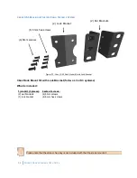
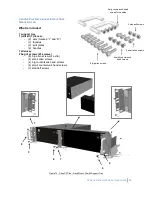
Page 54: ...k Bracket Cbox Rack Mount Kit with Lock Bracket for two L3 or S3 systems What is included 1 joint kit 3 pieces 2 sets of screws 2 ear brackets 1 lock bracket 4 6mm screws 4 6mm hex screws Please note that the allen or hex key is not included with the Cbox rack mount kit 4 6mm screws 4 6mm hex screws 2 Lock Bracket 2 Ear Brackets ...

Page 55: ...ocation of the two standoff screws on the left system circled in green Figure 68 Cbox L3 S3 Lock Bracket Identify Standoff Screws 2 Line up the two standoff screws on the left system and insert into the slots of the right system circled in green Figure 69 Cbox L3 S3 Lock Bracket Inserting into Slots 1 2 ...

Page 56: ...S3 Lock Bracket Attach Two Systems 4 Align the lock bracket holes to right side of the left system and the left side of the right system as pictured below Using a 2 5mm allen or hex key screw 4 6mm hex screws to securely attach the lock bracket to the systems Figure 71 Cbox L3 S3 Attaching Lock Bracket to Systems Please note that the allen or hex key is not included with the Cbox rack mount kit 3 ...

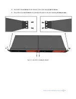
Page 57: ...IDE 57 5 Screw the first ear bracket to the left side of the system using 2 6mm screws 6 Screw the second ear bracket to the left side of the system using the remaining 2 6mm screws Figure 72 Cbox L3 S3 Attaching Ear Brackets 5 6 ...

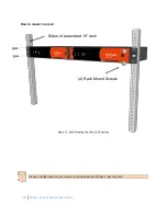
Page 58: ...ARDWARE USER GUIDE How to mount in a rack Figure 73 Rack Mounting Two Cbox L3 S3 Systems Please note that rack mount screws are not included with Winnov s rack mount kit Sides of a standard 19 rack 4 Rack Mount Screws ...

Page 59: ...K MOUNT INSTRUCTIONS SINGLE SYSTEM What is included 1 support tray 1 joint kit 7 pieces 2 ears marked L and R 2 façades 2 joint plates 2 handles 1 allen key 2 bag of screws 23 screws 8 big allen screws 4 extra 4 small allen screws 4 big countersunk head screws 4 small countersunk head screws 3 standoff screws Figure 74 Cbox S3 Plus Rack Mount Kit with Support Tray 1 2 3 4 5 6 7 8 9 ...

Page 60: ...o the right side of the system by inserting the standoff screws into the holes and sliding the support tray toward the rear 6 Remove the front right allen screws from the system then screw the left side of the joint plate to the system with 2 big allen screws 7 Screw the right side of the joint plate to the support tray with 2 small allen screws 8 Line up the handle with the corresponding holes of...

Page 61: ...RACK MOUNT INSTRUCTIONS SYSTEM SYSTEM What is included 1 support tray 1 joint kit 7 pieces 2 ears marked L and R 2 façades 2 joint plate 2 handles 1 allen key 2 bag of screws 25 screws 8 big allen screws 4 small allen screws 4 big countersunk head screws 4 small countersunk head screws 5 standoff screws Figure 76 Cbox S3 Plus Two System Rack Mount Kit Please note that the System System rack mount ...

Page 62: ...ft side of system 2 to the right side of system 1 by inserting the standoff screws into the holes and sliding system 2 toward the rear 12 Remove the front right allen screws from system 1 13 Remove the front left allen screws from system 2 then screw the left and right side of the joint plate to system 1 and system 2 with 4 big allen screws 14 Line up the handle with the corresponding holes of the...

Reviews: