background image

WiNRADiO G315 User’s Manual


83 


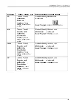
Windows 

Enable “speaker” icon  Recording/playback volume controls 

98 

Control Panel | 
Multimedia 
Audio-tab 

Checkbox

: “Show 

volume control on the 
taskbar” 

Control Panel | Multimedia 
Audio-tab 

Sound Playback

: Click on 

 button 


ME 

Control Panel |     
Sounds  and  
Multimedia   
Sounds-tab 

Checkbox

: “Show 

volume control on the 
taskbar” 

Control Panel | Sounds  and  
Multimedia      Audio-tab 

Sound Playback 

à


Volume

 button 


2000 

Control Panel |      
Sounds  and  
Multimedia   
Sounds-tab 

Checkbox

: “Show 

volume control on the 
taskbar” 

Control Panel | Sounds  and  
Multimedia      Audio-tab 

Sound Playback 

à


Volume

 button 


XP 

Control Panel |      
Sounds  and  
Multimedia | 
Sounds-tab 

Checkbox

: “Place 

volume icon in the 
taskbar” 

Control Panel | Sounds  and  
Multimedia      Audio-tab 

Sound Playback 

à


Volume

 button 


Summary of Contents for G315

Page 1: ...WiNRADiO G315 VHF UHF Receiver User s Guide...

Page 2: ...reproduced or transmitted in any form or by any means without the written permission of the publisher Trademarks WiNRADiO G3 G315 and Radio Basic are trademarks of WiNRADiO Communications All other br...

Page 3: ...adapters must be used Operation with non certified cables power adapters and peripherals may result in interference to radio and TV reception Modifications Any changes or modifications to the WiNRADiO...

Page 4: ...l Tuning Pad 19 Tune To Peak 19 AFC Automatic Frequency Control 20 Frequency Stepping 20 The Demodulator 22 Selecting Demodulation Mode 22 Real time Spectrum Scope 23 Setting and Adjusting IF Bandwidt...

Page 5: ...ower Switch 58 Date and Time Display 58 Spectrum Sweep Functions 59 Spectrum Analyzer 61 Activity Monitor 65 Signal Strength Logger 66 Scheduler 68 Calibration 73 Display offset 74 Front Panel LED 75...

Page 6: ...5 receiver transforms any modern PC desktop into a sophisticated VHF UHF monitoring station offering surprising power and flexibility and enjoyment of use We hope you will like the spectrum analyzer w...

Page 7: ...SMA type 50 ohm and an audio output The audio output is compatible with a PC sound card Line input or can be simply connected directly to an amplified multimedia speaker or any other suitable audio e...

Page 8: ...n SMA type connector with 50 ohm impedance The USB interface is compatible with both USB 1 0 and 2 0 standards and serves to connect the receiver to a desktop or a laptop computer Did you know The USB...

Page 9: ...stem Requirements Minimum Recommended CPU 500 MHz Pentium III 1GHz or higher Pentium IV or Athlon RAM 64 MB 256 MB or more Display SVGA SVGA 16 mil colors HD free space 20 MB 40 MB Sound card SoundBla...

Page 10: ...io jack and the sound card Line Input If there is no Line input on your PC as is the case with some laptops you may use alternative inputs such as the Microphone input Or if you prefer you can connect...

Page 11: ...installing the drivers choose the Run command from the Start menu in Windows and type D INSTALL if the CD ROM is the D drive on your PC 3 This will run the application installer which will guide you...

Page 12: ...ould be physically connected to the Line Input of the sound card Double click on the speaker icon in the task bar to bring up the sound card Volume Control panel Make sure the Line In input is not mut...

Page 13: ...e gratification only It is not intended to replace a proper antenna The best placement of the start up antenna depends on your actual situation and will often involve some experimentation However the...

Page 14: ...ope you will return to these chapters as the WiNRADiO G315 receiver has many fine features which would be a shame to miss Start the WiNRADiO G315 receiver application by double clicking on the WiNRADi...

Page 15: ...will see the cursor change to a curved double ended arrow Hold down the right or left mouse buttons to increase or decrease the frequency and the knob will rotate clockwise or anti clockwise respecti...

Page 16: ...Frequencies outside the receiver limits 9 kHz to 1800 MHz will not be accepted and the display will revert to the previous frequency Use the kHz or MHz buttons to select how you wish the frequency to...

Page 17: ...allocations for entire frequency bands This can be done by editing the file called bands csv in the WiNRADiO installation folder This is a standard comma separated value format file which can be edit...

Page 18: ...Simply press either the right or left mouse button As the knob rotates the frequency will change in 500 Hz steps Holding the mouse button down will accelerate the tuning The step size can be changed t...

Page 19: ...invoked by pressing the TTP button The receiver will tune to the signal peak provided the peak falls inside the selected IF bandwidth the highlighted area of the real time frequency spectrum Dependin...

Page 20: ...value from 1 Hz to 1 MHz You can also use the up and down buttons on the right of the display to select from commonly used step sizes For convenience you can also use the small slider between the two...

Page 21: ...to stepping will automatically set the step size according to the frequency you are tuned to Auto stepping can be also used to associate particular mode and squelch settings with specified frequency r...

Page 22: ...rol IF filter bandwidth IF shift RIT software AGC AF squelch notch filter noise blanker recorder playback and real time spectrum display are grouped together in an area of the front panel of the recei...

Page 23: ...on within the bandwidth of the receiver The spectrum scope shows an area of 20 kHz wide as defined by the receiver s roofing filter The IF intermediate frequency bandwidth and center frequency is soft...

Page 24: ...WiNRADiO G315 VHF UHF Receiver 24 Spectrum trace without video filter The same signal with video filter set at 3300 Hz...

Page 25: ...ts represented by the row of buttons at the bottom of the demodulator window The numbers on the buttons represent bandwidth in kHz The preset frequencies change according to the mode selections All th...

Page 26: ...between the up down cursor keys and move it up or down This is quite a fast and convenient method Another very convenient method is to adjust the IF bandwidth graphically on the real time spectrum dis...

Page 27: ...inactive filter edge is shown in a darker color The IF Shift facility makes it possible to quickly and visually tune to another station represented by a signal peak in the real time spectrum However...

Page 28: ...volume To enter a value directly click on the display and type in the new volume level The volume can be also increased or decreased by clicking on the up down buttons next to the volume display Anot...

Page 29: ...with which the AGC reacts Typically the AGC would be in the Medium position The timing of slow medium or fast speed settings is user definable under the Setup button The attack time the speed with wh...

Page 30: ...4 If the sound is too weak when SAGC is disabled and yet the volume control is all the way up use the Audio gain setting to increase the level Notch Filter The notch filter is a band stop filter whic...

Page 31: ...r In the resulting audio typically there would be a strong buzzing sound After engaging the notch filter and adjusting its center and bandwidth by dragging the blue area center and edges to fall exact...

Page 32: ...e emphasis of high frequencies It is also useful to remove low frequency audible tones of CTCSS squelch signalling The Audio filter is activated using a button at bottom right of the demodulator panel...

Page 33: ...rics The Noise Blanker is activated by pressing the Blanker button If the instantaneous IF signal level exceeds the specified Threshold level those IF samples are replaced with older ones The threshol...

Page 34: ...signal is of some significance and needs to be analyzed A weak or interference obscured signal can be thus re received with different bandwidths notch filter and noise blanker settings to arrive at t...

Page 35: ...path can be set up using the Path edit box The default file names for recording playback can be set up using the Audio file and IF file edit boxes for Audio files and IF files separately The directory...

Page 36: ...ate time frequency etc inside the name of the file The following wildcards are supported D system date in YYYYMMDD format T system time in HHMMSS format F frequency in MHz 6 decimals M mode AM AMS DSB...

Page 37: ...pressing the Test button This causes an instrumentation window to open which contains several facilities to assist with analysis and measurement of the received signal The real time Audio Spectrum Ana...

Page 38: ...o remain on top of all other windows Did you know Using the SINAD measurement facility and a calibrated signal generator you can measure the receiver sensitivity very easily For example to measure AM...

Page 39: ...offers additional measurement facilities This function is intended for users wishing to acquaint themselves more deeply with Software Defined Radio principles It is described in greater detail in App...

Page 40: ...this feature to provide an output to a secondary real sound card The last remaining demodulator settings are Mute audio on exit and Show frequency in kHz located at the bottom left of the demodulator...

Page 41: ...with CW signals where information is transmitted by keying the transmitter on and off the signal strength will vary substantially during the transmission The demodulated signal will then sound better...

Page 42: ...abled when the AGC is switched off The gain can be adjusted in three ways by typing the value directly in the edit box by using the up and down buttons or by dragging up or down the centre slider butt...

Page 43: ...elch determines the level of noise in the received demodulated audio below which the squelch will open and unmute the receiver This is particularly useful for the FM mode where there is a considerable...

Page 44: ...n the band Now when you tune to an occupied frequency if its signal strength is higher than the squelch level the receiver will be unmuted To adjust the Noise squelch control first tune to an unoccupi...

Page 45: ...you also wish to store the mode Next click on the S button in the Memory Control Panel as shown above A Store frequency dialog box will pop up making it possible to assign a memory number to the curre...

Page 46: ...quencies can be stored in each memory file Then follow the current frequency IF shift and bandwidth parameters You can alter these if you wish The third item contains the group assignment buttons You...

Page 47: ...tored with a frequency The size of the comments is limited to 31 characters The Mode and Squelch values can also be stored which will then be set automatically when the frequency is recalled Finally a...

Page 48: ...o change the settings for a particular frequency open the Recall frequency dialog box as described in the previous section Select the item you want to edit and click on Edit alternatively double click...

Page 49: ...cation starts up the most recently used memory file will be opened automatically To open a different memory file select Open from the Memory file sub menu in the File menu A dialog box will pop up all...

Page 50: ...se button marked with two vertical bars A signal is considered found when it satisfies the squelch conditions For example if Level squelch is selected then the signal level must be higher than the spe...

Page 51: ...ich the scanning will Resume The conditions to resume can be one of the following When the signal disappears i e the scanning resumes immediately when the signal disappears After Delay time i e no mat...

Page 52: ...the pre set Delay time to expire the countdown timer will appear inside the or buttons If no Delay time was set and scanning is pausing until the signal disappears then the or button will flash Group...

Page 53: ...to include in range scanning A very useful feature of frequency range scanning is that all found frequencies can be automatically stored in memory even if the receiver is left unattended To do this en...

Page 54: ...e Range button in the Scanning control panel When you press the Scan Forward button the scanner will commence scanning from the start frequency of the first range When the last frequency of the first...

Page 55: ...there is no value stored the current squelch value will be used as the scanning threshold It is possible to restrict scanned frequencies to particular memory groups only These groups can be selected...

Page 56: ...gnal strength falls under the squelch level i e the needle falls in the red region and turns red also the receiver audio will be muted The squelch value is always indicated in dBm even if the signal s...

Page 57: ...operation Therefore if the AGC is switched off and manual IF gain is used instead the S meter is also disabled Did you know There are no exact definitions for S units merely recommendations Historica...

Page 58: ...d Time Display The clock display at the top right corner of the application window indicates the current time and date The display can show either UTC time or local time To switch between the two mode...

Page 59: ...e left of the On Off switch If the upward pointing arrow button is pressed the large sized full screen spectrum sweep display will slide out upwards entirely obscuring the receiver main control panel...

Page 60: ...rsion also contains a basic set of the receiver controls at the top so that the user does not need to go back to the receiver panel to change mode volume attenuator etc Unlike the spectrum scope insid...

Page 61: ...Resolution Bandwidth which determines how detailed the spectrum will be the lower the RBW the finer the detail The finest RBW is 15 625 Hz The RBW has a proportional effect on the spectrum sweeping sp...

Page 62: ...h a red cursor will appear Clicking anywhere on the spectrum graph tunes the receiver to the corresponding frequency You can also drag the mouse horizontally across the spectrum and continuously tune...

Page 63: ...ul when investigating activity on a given band The receiver can be left unattended in the continuous sweeping mode and any activity on the band will be clearly visible on the differential trace Note t...

Page 64: ...done with respect to the center of the screen The next two buttons perform the actual zooming in and out functions Spectrum sweeps can be opened and saved using file manipulation buttons To hide the...

Page 65: ...quency range A hit is an instance when the signal satisfies the squelch conditions for the given frequency This makes it possible to observe and monitor traffic on particular channels over a period of...

Page 66: ...ive bar will turn red for the rest of the scan This is designed to give you a visual idea of current activity in the band Signal Strength Logger The Logger makes it possible to record signal strength...

Page 67: ...ilar to this Interval 00 01 00 Atten Off Preamp On Peak 101 9 468 125 808 red green yellow 99 9 120 0 75 1 99 8 120 2 75 2 100 1 120 1 74 9 99 9 80 1 74 9 99 8 80 2 75 1 99 8 80 2 75 1 etc The first l...

Page 68: ...hich runs repetitively The rest of the line text shows some basic parameters of each task such as the starting date and time the frequency and the status The status information can be one of the follo...

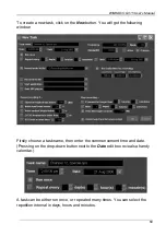
Page 69: ...he following window Firstly choose a task name then enter the commencement time and date Pressing on the drop down button next to the Date edit box reveals a handy calendar A task can be either run on...

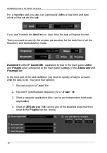
Page 70: ...s the IF bandwidth equivalent to that in the main panel Atten and Preamp also correspond to the main panel settings of the Attenuator and Preamplifier In the next part of the task definition you need...

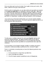
Page 71: ...ing tasks you can also specify situations where the recording should pause in order to save disk space and also to cut out long pauses when playing back The five pause conditions replicate the main pa...

Page 72: ...dit a currently running task you need to stop it first using the Stop button If a task is stopped it will remain in the task list until either continued or deleted manually The Stop and Continue butto...

Page 73: ...arge temperature changes or long term component aging Access to this facility is provided via the Options top bar menu Upon selecting the Calibration function the following window appears The S meter...

Page 74: ...ed with the receiver for example the WiNRADiO WR DNC 3500 downconverter which makes it possible to receive signals up to 3 5 GHz on the WR G315 receiver This facility is selectable under the Options m...

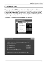
Page 75: ...especially for installing the receiver and debugging possible interfacing problems see Appendix J The behavior of the LED in its normal receiver ready state can be controlled by the user making it pos...

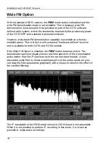
Page 76: ...is in fact a self contained hardware defined receiver and is available for both G315i and G315e models If the Wide FM Option is installed the FMW button becomes active The demodulator spectrum displa...

Page 77: ...e Attenuator is off Preamp is on and AGC is set to medium With G315e receiver the sound is coming via the Windows Wave device Make sure that this is unmuted in the sound card control panel and the sou...

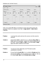
Page 78: ...on Check if the AGC is switched on i e either the Slow Med or Fast buttons are pressed usually the medium setting should be used Also set SAGC to Med In the demodulator Setup adjust the SAGC reference...

Page 79: ...but the spectrum scope display is very sluggish sometimes it even freezes Solution Close all other simultaneously running programs to reduce the burden on the CPU This may indicate insufficient CPU re...

Page 80: ...f if the interference disappears then the cause is the monitor Modern LCD monitors generate much lower levels of interference than CRT ones See also Appendix C Dealing With Interference Problem I mana...

Page 81: ...ial number of the receiver Your Height value is probably greater and you should change it to a reasonable value about 200 Did you know The G315 receiver can be also controlled remotely and the audio s...

Page 82: ...t is not available The output volume is controlled by the Playback volume control of the sound card Typically you would access the Playback volume control panel by clicking the speaker icon in the Win...

Page 83: ...imedia Sounds tab Checkbox Show volume control on the taskbar Control Panel Sounds and Multimedia Audio tab Sound Playback Volume button 2000 Control Panel Sounds and Multimedia Sounds tab Checkbox Sh...
Page 84: ...to operate this creates a potential paradox The WiNRADiO receiver itself is designed to be substantially immune to PC interference However any receiver needs to be connected to an antenna and antenna...

Page 85: ...ons whose frequencies combine to create ghost signals on frequencies which are arithmetic combinations of the stations frequencies These ghost signals can sometimes coincide with useful frequencies re...

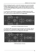
Page 86: ...the Demodulator function is fully performed in software The receiver hardware contains the following functional blocks The incoming signal from the antenna in the 9 kHz to 1800 MHz range is filtered a...

Page 87: ...ed until the dynamic range of the first IF stage is fully utilized this is in order to prevent desensitization of the receiver in the presence of neighbouring strong signals falling within the 20 kHz...

Page 88: ...egree offset usually referred to as I Q AM Demodulator Structure The demodulator structure windows include two spectrum analyzers making it possible to view signal spectra in real time Each analyzer c...

Page 89: ...ectral components at the cursor frequency For synchronous demodulation of amplitude modulated signals the AMS mode without carrier or with a fluctuating one the G315 demodulator uses a PLL carrier rec...

Page 90: ...convenient audio frequency This frequency a digital BFO is user adjustable by changing the value of the CW tone frequency parameter in the demodulator setup CW Demodulator Structure Finally the freque...

Page 91: ...we have developed a special interfacing standard called XRS Extensible Radio Specification All our receivers conform to this standard and many plug ins are already available for various applications...

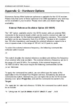
Page 92: ...nal to be a sine or square wave in the range of 100 mV to 5 V peak to peak To select the external reference frequency the following command line software switch is used c This switch disables the inte...

Page 93: ...ement If the receiver relies on its internal reference oscillator this option will provide 16 384 MHz reference output If an external oscillator is used then the external oscillator frequency will be...

Page 94: ...0 kHz instantaneous bandwidth of the digitized IF signal and the DSP software processing power The WFM option is in fact a self contained hardware defined receiver The user can receive wide FM broadca...

Page 95: ...ct us at www winradio com enquiry for details Did you know The idea of processing radio frequency signals by converting them to an intermediate frequency first i e the superheterodyne principle is att...

Page 96: ...the internal reference oscillator in Hz This is normally 16 384 MHz i e 16384000 Hz Each receiver is factory calibrated so a fundamental correction to the nominal 16 384 MHz reference frequency alrea...

Page 97: ...he WRG315 ini file You can also delete the entire file which will however result in losing all current receiver settings and return to factory defaults for all of them Did you know The WWV Time and Fr...

Page 98: ...315 The S meter Calibrator requires the use of a precisely calibrated synthesized signal generator to generate calibration levels in the frequency range of interest It possible to create calibration t...

Page 99: ...radio off 4 One short flash followed by a long one USB connected radio on receiver ready 5 Two short flashes followed by a long one USB connected driver not installed 6 Three short flashes USB connect...

Page 100: ...WiNRADiO G315 VHF UHF Receiver 100...

Reviews: