WR-G35DDCi Multichannel Coherent Application Guide for Extended topology configuration (ETC)
10
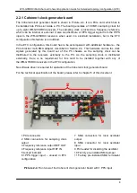
2.2.5 Frequency reference output REF OUT
The frequency reference output is an SMA connector providing the 10 MHz (internally
derived) frequency reference output signal. This output can be connected to the REF IN input
port (Section 2.2.6) if the internal frequency reference operation of the board is required. Use
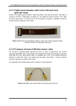
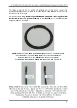
the Frequency Reference SMA Interconnect cable (described in Section 2.2.12 and provided
with the Clock Kit) to connect the REF OUT port to the REF IN port.
If unused, this port must be properly terminated using the 50 ohm terminator.
For the technical specification of the REF OUT, please refer to Chapter 5.
2.2.6 Frequency reference input REF IN
A signal provided to the frequency reference input REF IN serves as a frequency reference
for the 100 MHz sampling clock generator. It is a 50 ohm terminated SMA connector.
A 10 MHz reference signal must be provided on this input.
This input can be connected to the REF OUT output port (Section 2.2.5) if the internal
frequency reference operation of the board is required. Use the Frequency Reference SMA
Interconnect cable (described in Section 2.2.12 and provided with the Clock Kit) to connect
the REF OUT port to the REF IN port.
For the technical specification of the REF IN input, please refer to Chapter 5.
2.2.7 1PPS trigger input
The 1PPS trigger input is unused in the ETC configuration and has to be left unconnected
when operating in the ETC configuration.
2.2.8 Locked indicator
The ‘Locked’ indicator is lit whenever the 100 MHz sampling clock generator is locked to
the frequency reference signal provided at the REF IN port. For more information about the
REF IN port please refer to Section 2.2.6.

