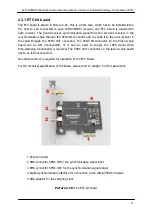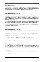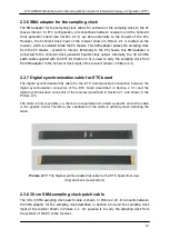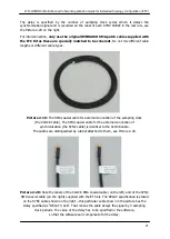
WR-G35DDCi Multichannel Coherent Application Guide for Extended topology configuration (ETC)
13
2.2.13 SMA terminators
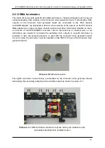
The Clock Kit comes with eight 50 ohm SMA terminators. These terminators must occupy all
unused sampling clock outputs on the Coherent clock generator board. If all sampling clock
outputs on the Coherent clock generator board are connected to the
‘PCIe bracket
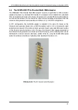
multi-SMA adapter
’ (as described in Section 2.4) and some of the outputs on the PCI bracket
SMA adapter are unused, all these unused outputs must have terminators installed on them.
A minimum of two WR-G35DDCi receivers can be connected as a coherent pair, so six
terminators are needed to terminate the sampling clock outputs. A seventh terminator is
provided in case the external reference is used with the Coherent clock generator board.
In such a case, the terminator must be installed on the REF OUT port of the Coherent clock
generator board.
Picture 2-10:
SMA terminators
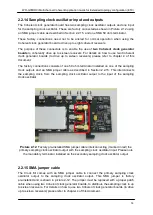
The eighth terminator comes factory pre-installed on the Coherent clock generator board,
terminating the secondary sampling clock oscillator output as shown in picture 2-11.
Picture 2-11:
SMA terminator (marked in red) are factory pre-installed on the
secondary sampling clock oscillator output

